Raspberry PiBoy – Building a Handheld Gaming System from Walnut and Carbon Fiber

DESIGN
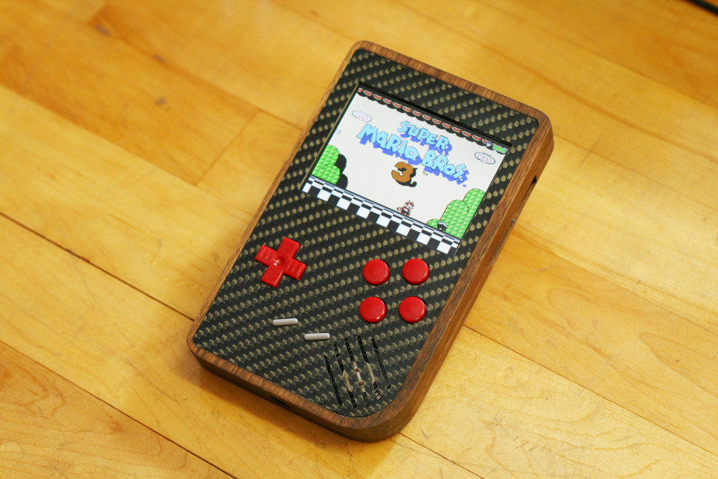
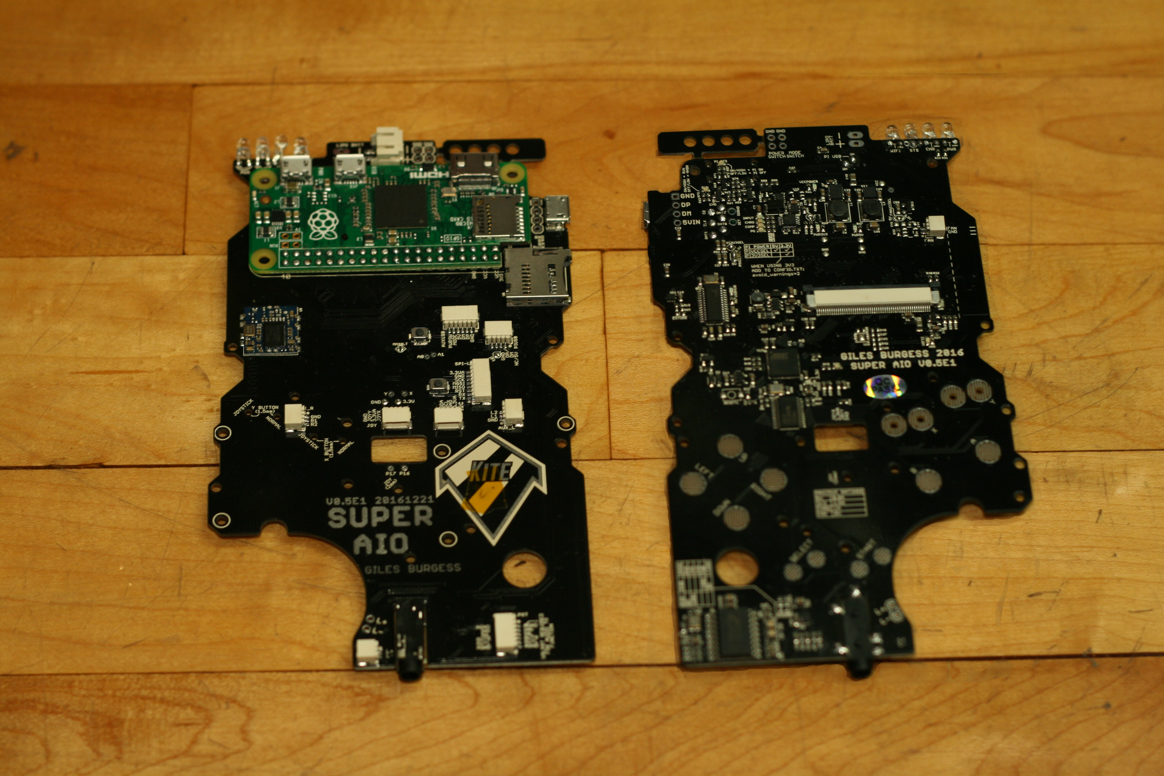
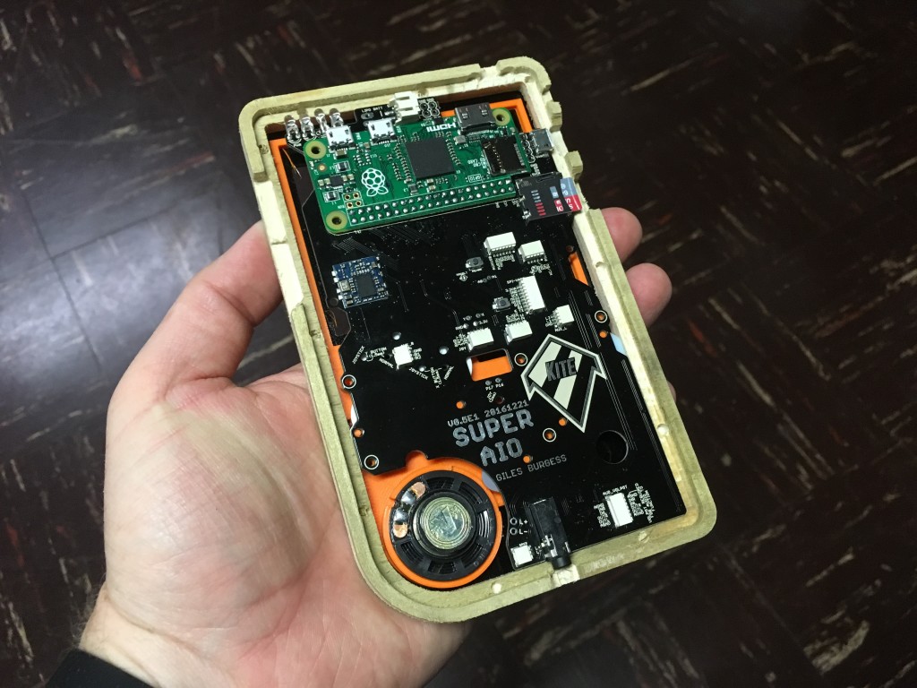
Portable Raspberry Pi enabled gaming system projects seem to be everywhere. The concept is relatively simple; get an old GameBoy (or other old portable) shell, stuff in a Raspberry Pi Zero as well as some switches, LiPo battery and charger, an LCD screen, and maybe an audio amplifier and you’re set (except for the giant mess of wires.) Recently, folks have taken to making customized circuit boards called “All-in-One” (AIO) boards to simplify the build but all still seemed to require a good deal of creative wiring. Then I came across a board on the SudoMod forums created by Giles Burgess (aka Kite) called “Kite’s Super AIO.” This board had nearly everything on it; provisions for an LCD screen, onboard ATMEGA 32U4 for button inputs, microSD slot, onboard battery charger, audio amplifier, volume control, external USB port, status LEDs, and more. And somehow Kite managed to make the board a near drop-in replacement for the original Nintendo GameBoy PCB so it’d fit with only minor modifications – even the ports lined up perfectly. So I pre-ordered two kits and waited until they arrived several months later, then I forgot about them..
At Maker Faire Bay Area 2017 my friends over at Vectric asked if I might be interested in attending their user group meeting in Las Vegas in October, with the caveat that I had to make and present a project using their software. Of course I said yes and remembered instantly about the boards. Since the electronics were already done I just had to design an enclosure. I wanted the device to maintain the 80’s charm of the original Nintendo GameBoy but look more “dapper” and timeless. I like the blend of carbon fiber and wood and wanted it to have a somewhat organic form that would be easy to hold for extended gaming sessions. So I started drawing the outline using Vectric’s Aspire CAD/CAM software and came up with this:
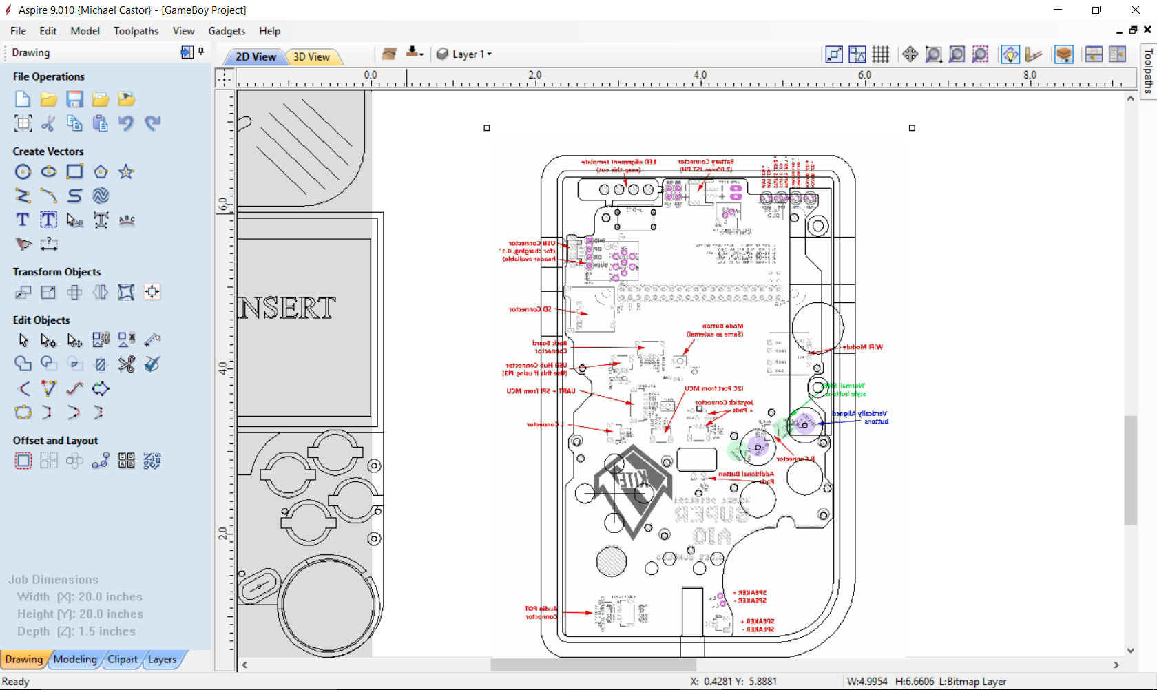
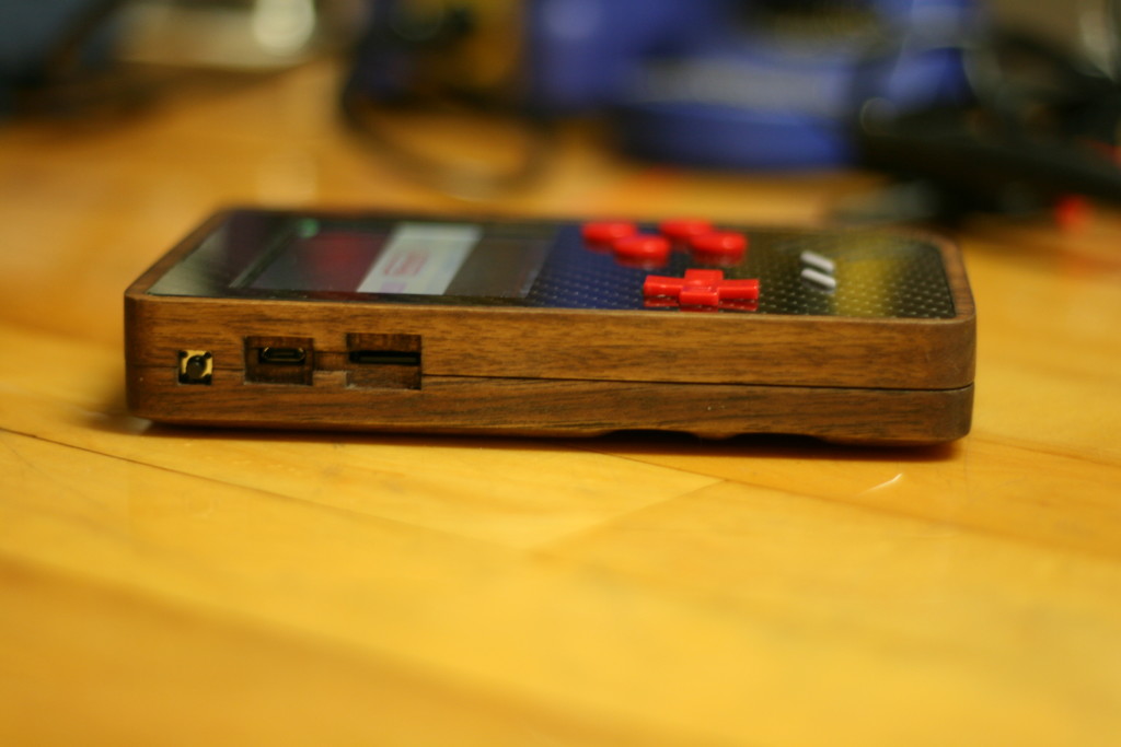
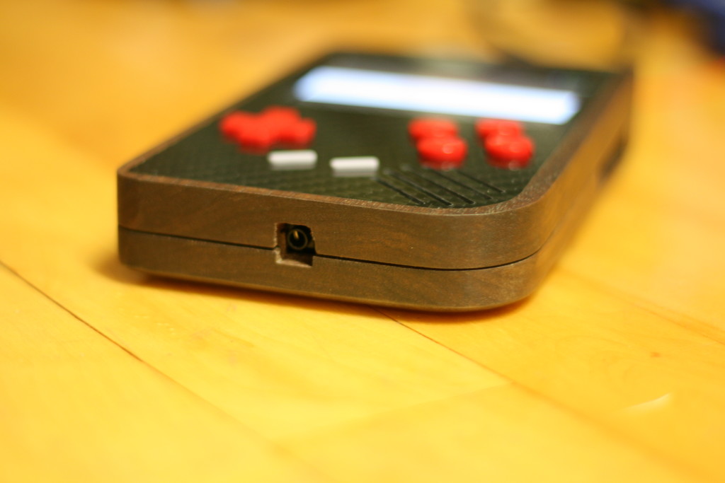
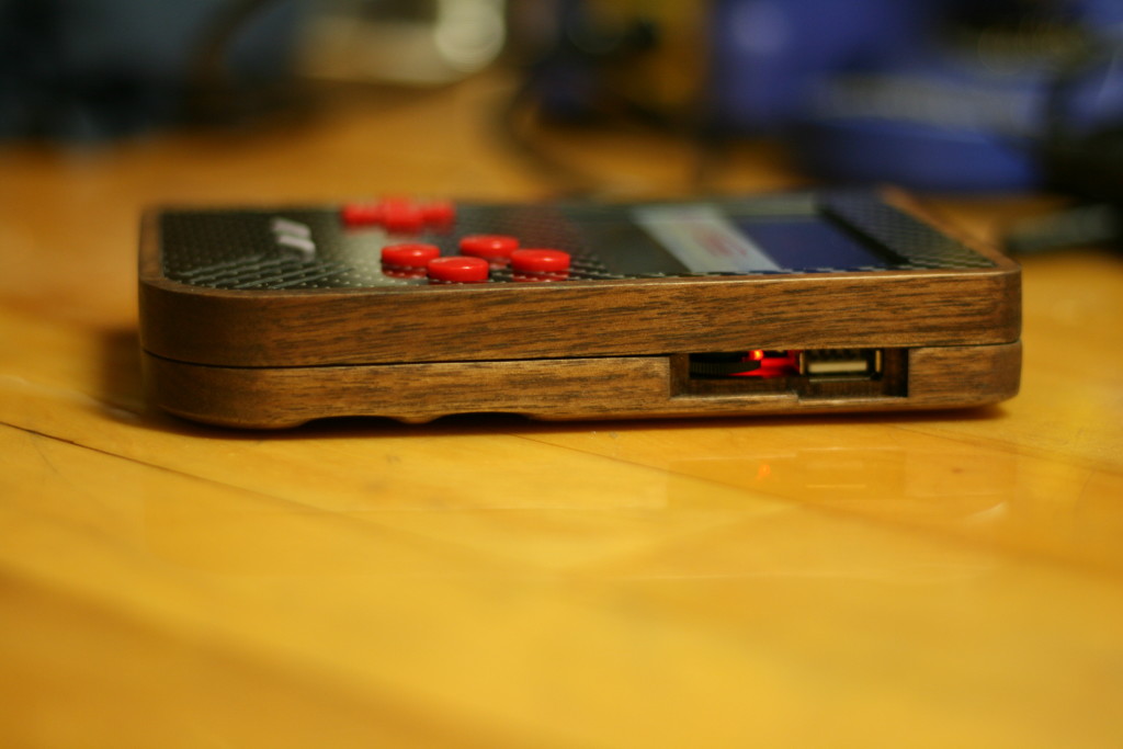
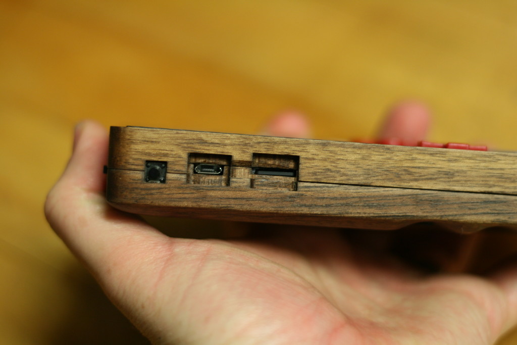
I drew the enclosure around the SAIO PCB so it would fit snugly into the enclosure with no wasted room. The top was offset and recessed so that a 1/16″ carbon fiber plate top-plate would sit flush with the bezel. Due to the thin (for wood) bezel, I decided to leave a 90 degree angle and forgo any round-overs as I was afraid there wouldn’t be enough material. Port locations were drawn in from a PDF of the SAIO PCB. Each port required two different depths and toolpaths, one barely larger than the component or port, and one the outside that was big enough a finger or whatever you needed to plug into it. Of course, these ports also needed to be on the back side of the enclosure and centered so they didn’t look funny. This was a frustrating, painstaking process that involved math, whiteboards, Excel, and the help of a friend. Eventually I (with help) ended up creating a formula that gave me the depths for each side.
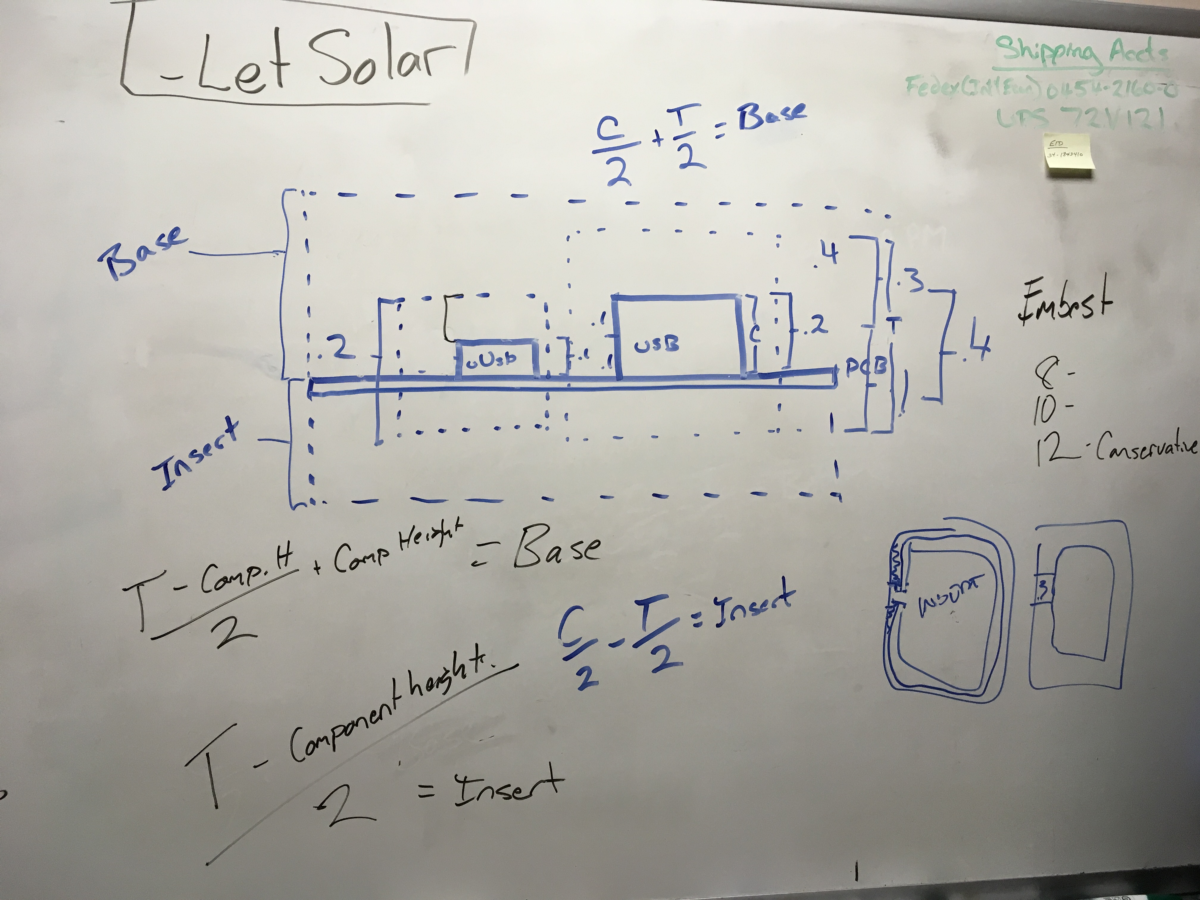
In case you can’t decipher, depth for the back = (Total Clearance – Component Height)/2 + Component Height. Depth for the top = (Total Clearance – Component Height)/2.
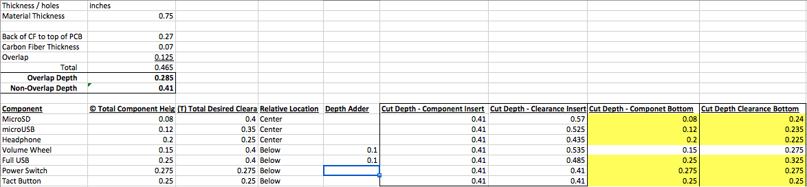
(Fortunately, you don’t have to worry about these formulas since I’ll share my files.)
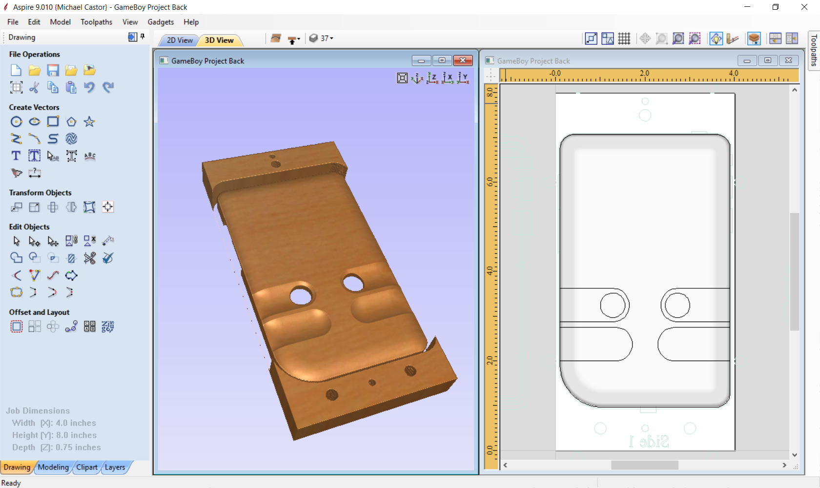
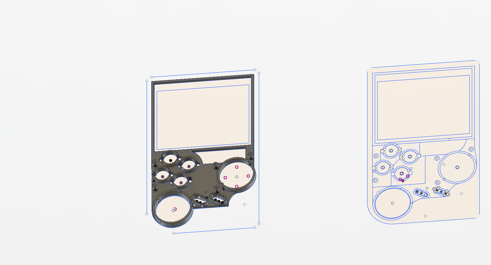
Here’s the render of the back of the front. Toolpath depths and heights were take from the Excel spreadsheet above.
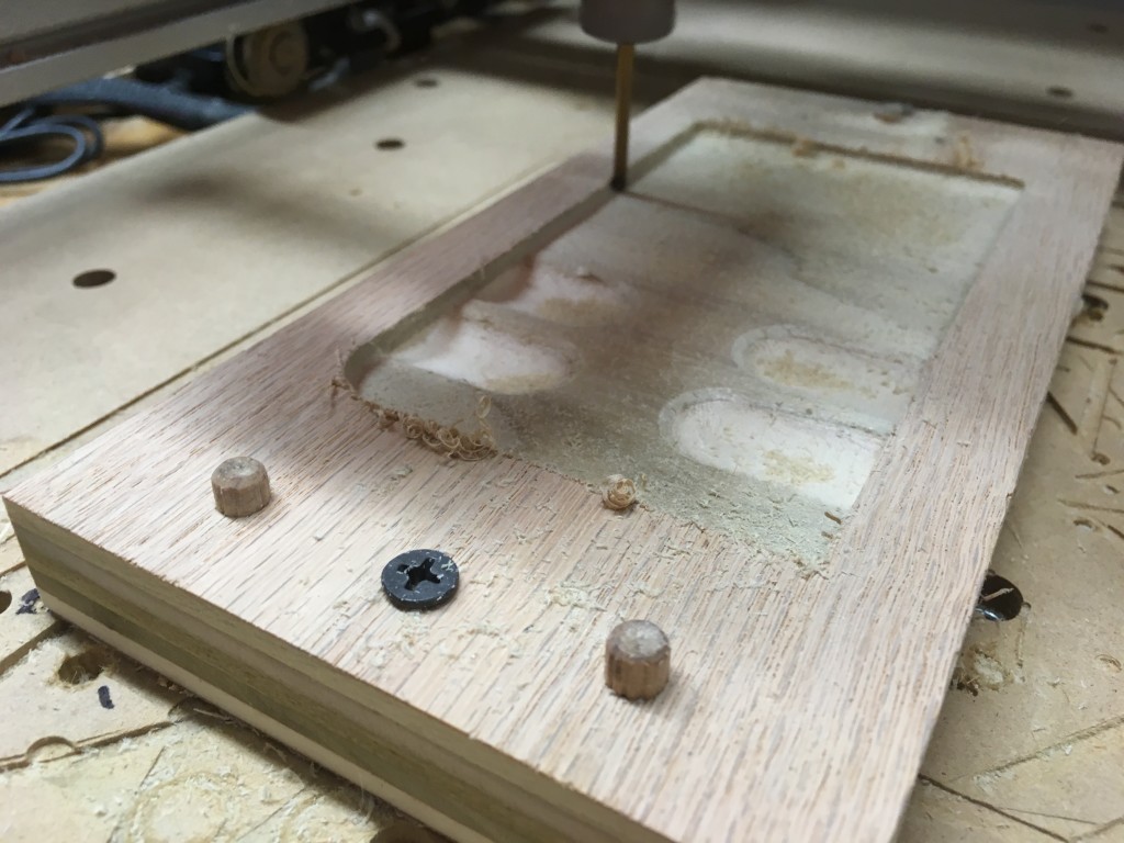
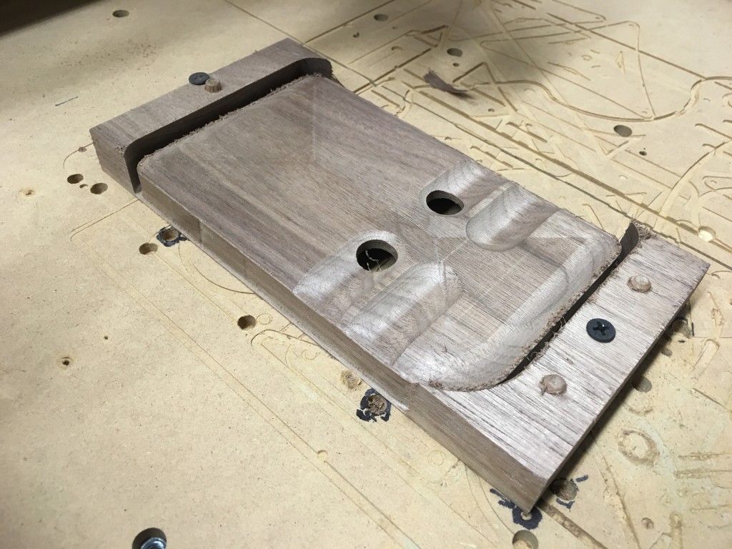
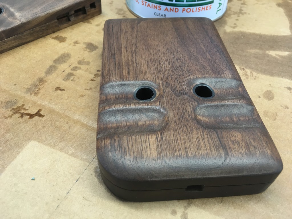
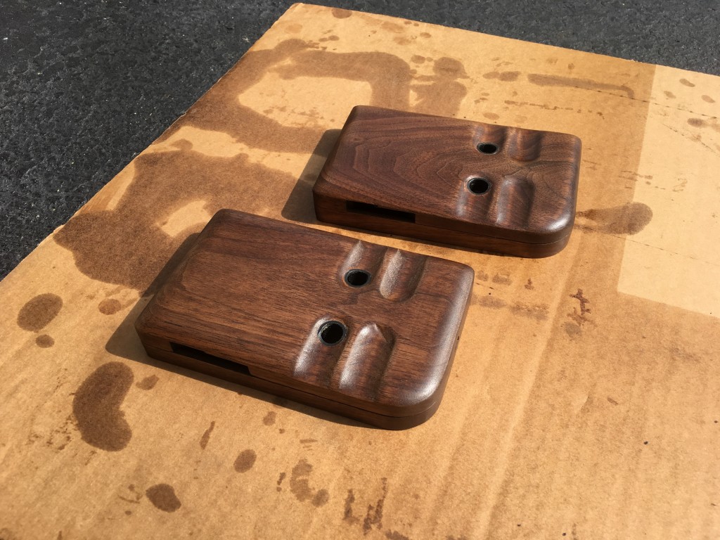
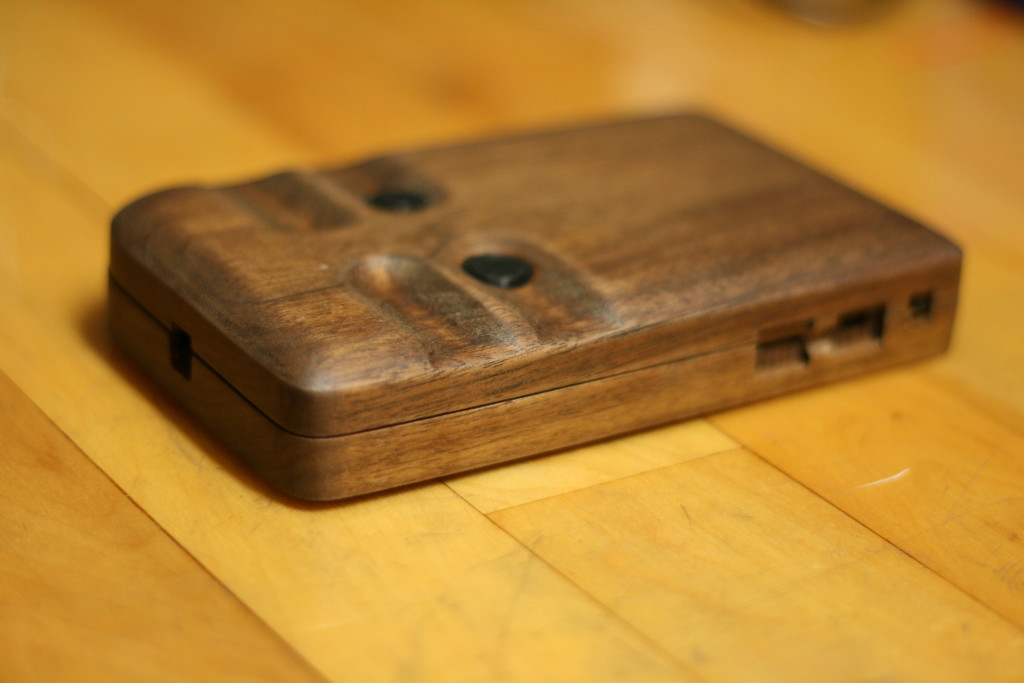
Next I started on the back. I wanted it to be smooth and organic-looking with indents that your fingers would naturally fall into. So I measured my fingers, measured where they naturally went to when holding an original GameBoy shell and created the following:
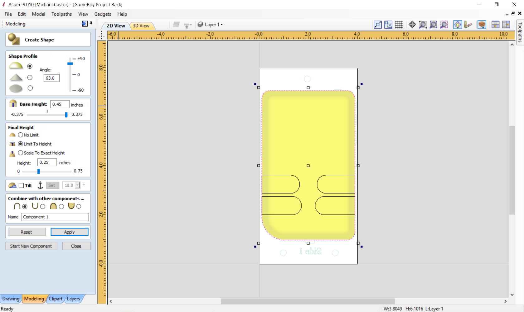
Vectric’s Aspire wins hands-down when it comes to getting organic shapes. Whenever I’ve tried doing anything like this with Fusion 360 I’ve failed miserably. It took me about 3min in Aspire to get it exactly the way I wanted.
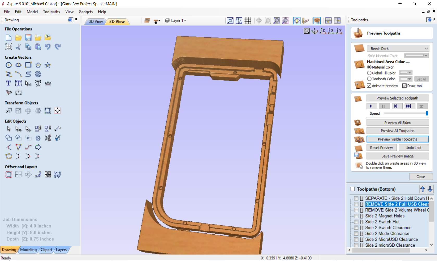
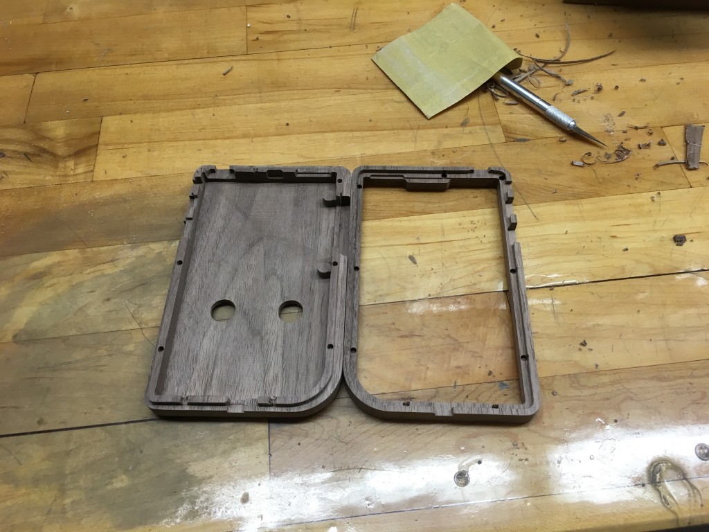
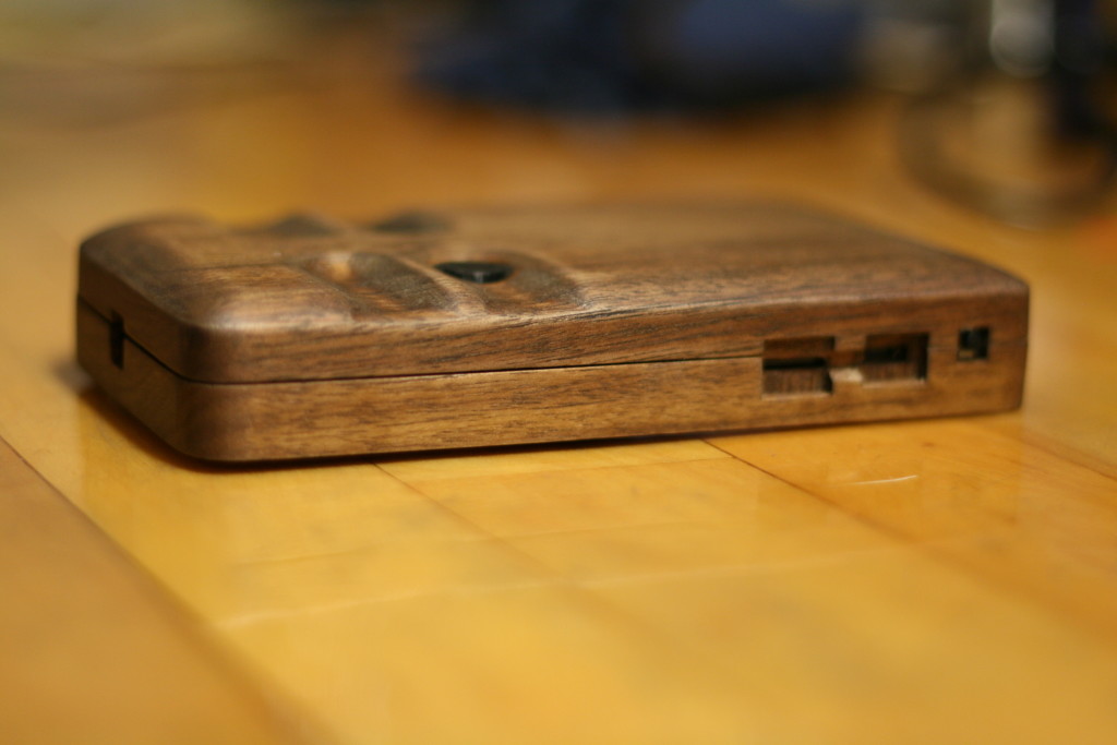
Once the back was complete I started on the front side of the back. A main pocket was created for the electronics to fit with supports for the “back board” PCB (a separate circuit board with volume control and USB port), an internal ridge to keep the device together, and individual pockets for each port on the PCB.
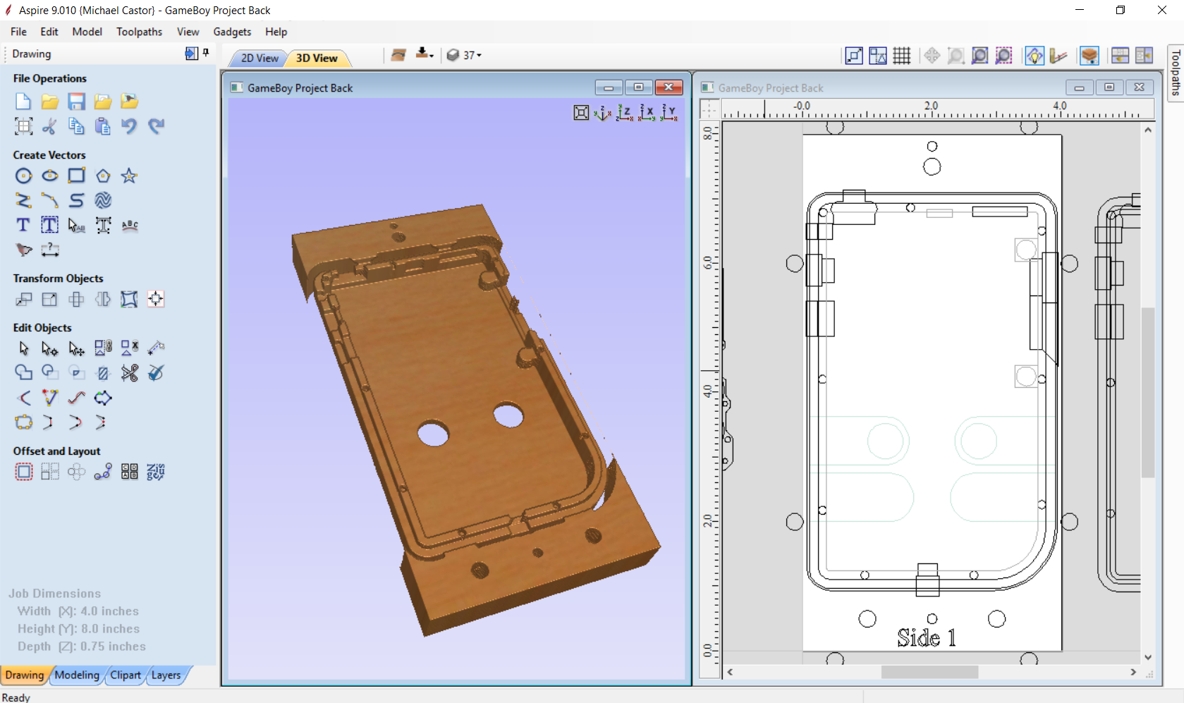
You’ll notice that I’m doing multi-sided machining. I’ve attempted this in the past and it never went well as all the drawings / toolpaths get confusing and inevitably I would screw it up. I tried it on the PiPad but gave up due to countless headaches. Thankfully Vectric recognized what a nightmare this can be and created a “flip side” button in Aspire 9.0. Clicking this button “flips” the view to the back side of your project and lets you copy over lines or draw new ones. Lines not on the active side are a turquoise color, helping you keep track of what’s going on. It also organizes toolpaths per side which is amazing. Can you tell I like this software?
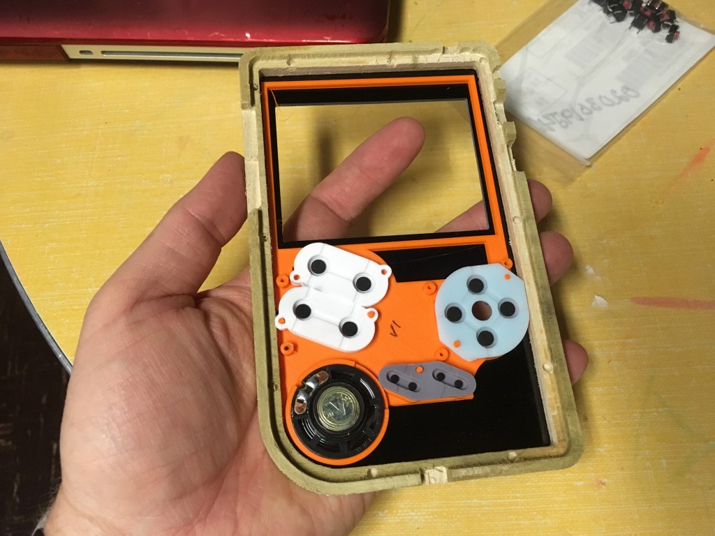
Once the CNC files were created I had another issue to contend with. The original GameBoy shell had integrated button wells molded in. These wells keep the buttons properly oriented, hold the rubber membranes in place, and provide the correct spacing required for the conductive bits on the membranes to interact with traces on the PCB to register a button press. My solution was to model an insert in Fusion 360 using measurements taken from an original GameBoy shell. I also added provisions to hold the screen in place squarely in front of the viewing window, hold the speaker, and integrate the screw-holes and locators for the PCB just like the original.
Thanks to the DXF file Kite provided I was able to get everything right where it needed to be. It took several prototypes to get the heights correct but finally I had something that worked.
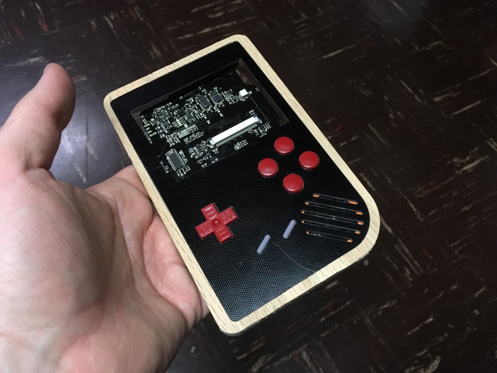
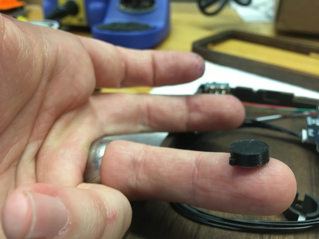
I had one more issue to take care of after this. I wanted to add the “shoulder” buttons on the back of the wooden enclosure but had to figure out a way to do it. After racking my brain to try to figure out how to use GameBoy buttons I gave up and decided to design and 3D print my own.
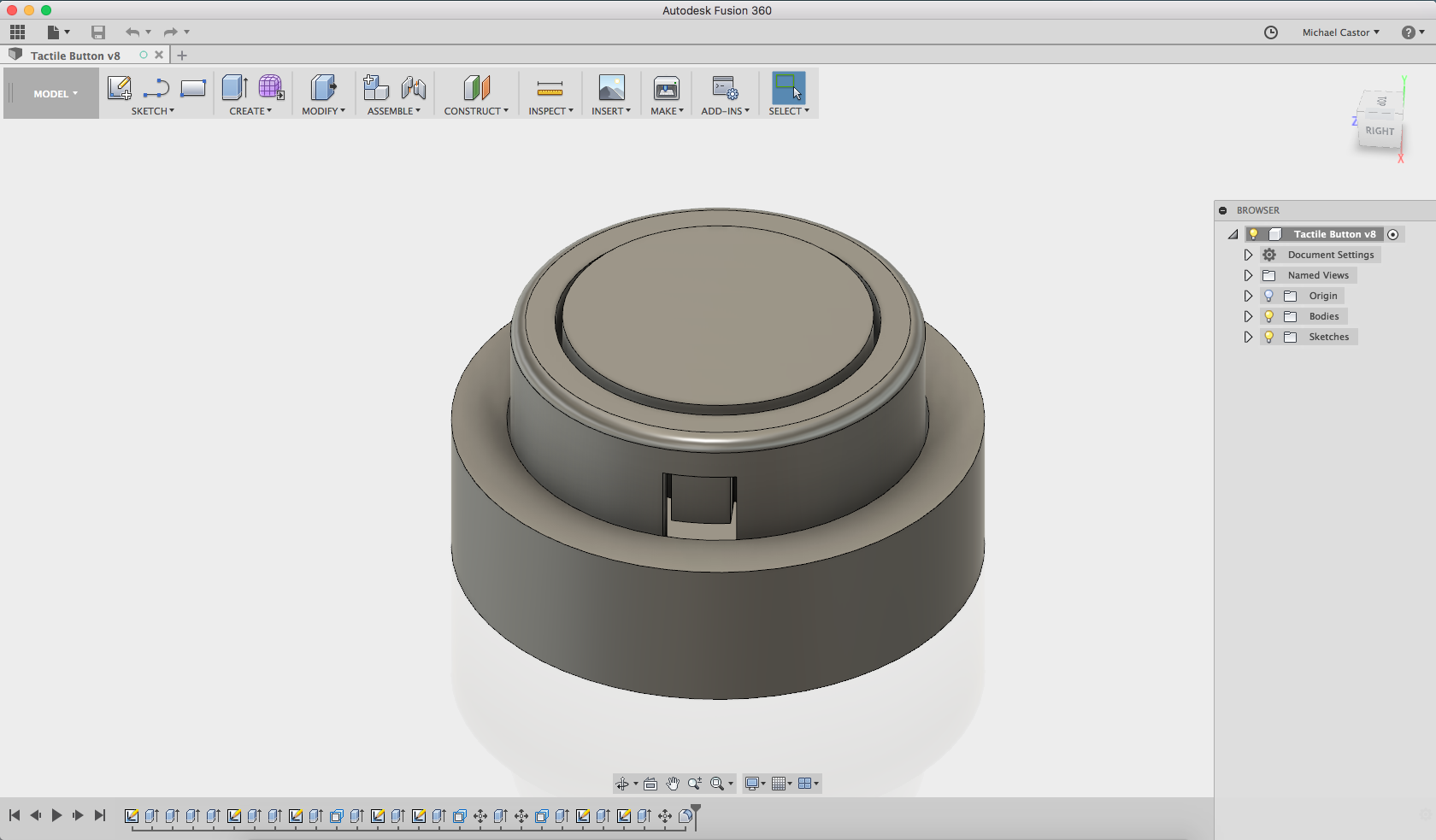
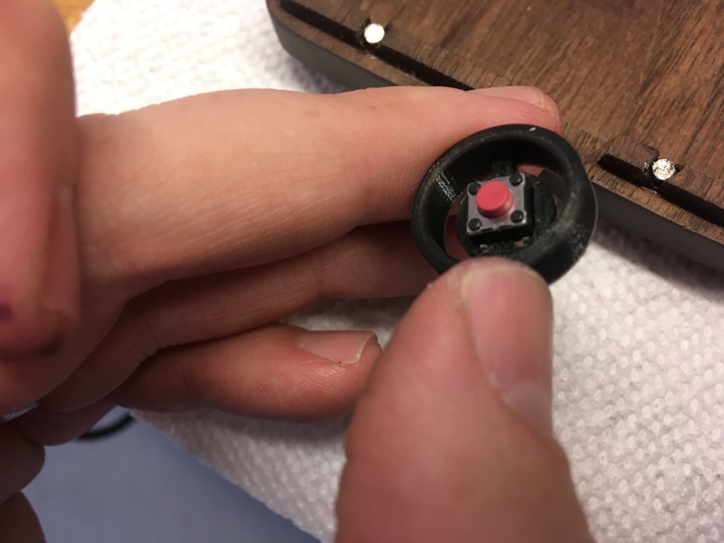
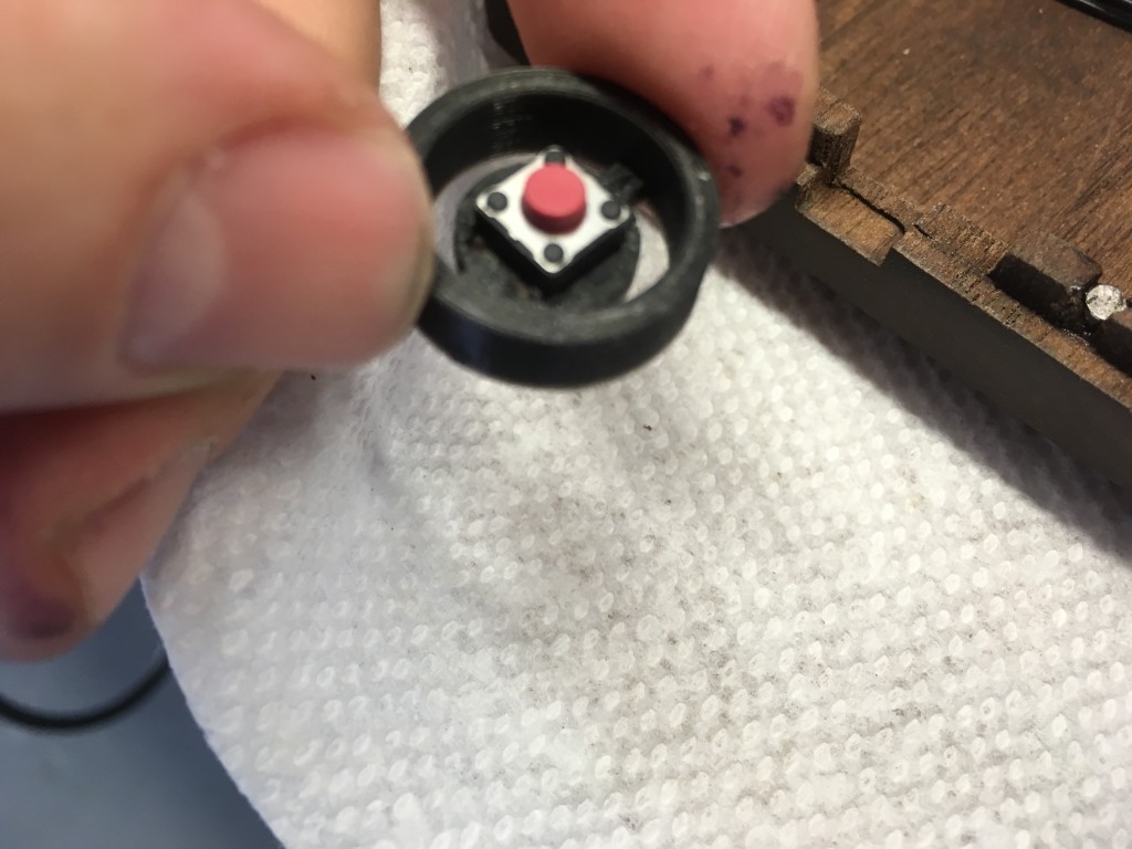
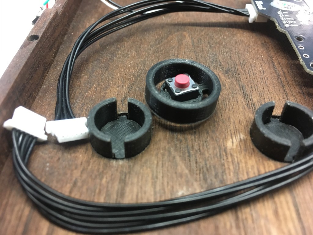
This button is in 3 pieces; the actual button, a well that will get glued into the wooden shell, and a backing to keep everything in place. Embedded inside is a common 6mm x 6mm tactile switch to give a nice “clicky” feel when pressed and act as a spring.
MACHINING
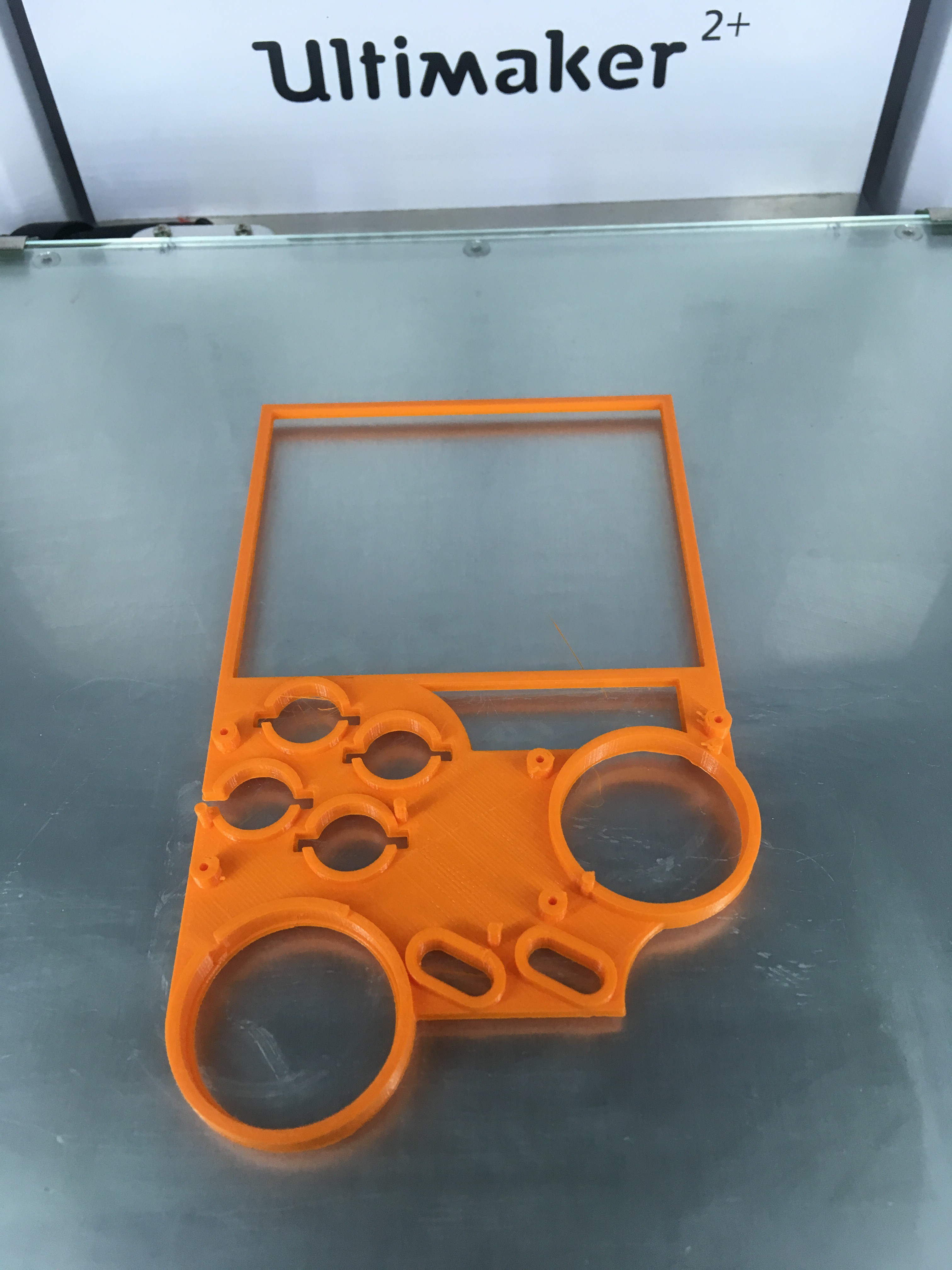
Once the files were complete I set off on machining. Like all great makers who don’t like to waste good material, I made a prototype using scrap plywood and some G10 fiberglass left over from a drone project. I cut every first to verify that it would work before using the good (expensive) stuff.
When making the prototype I learned several things; first, I made the back far too thin. I could actually feel my fingers press through the finger indents. Second, the volume and USB port locations were too high and needed to be almost flush with the pocket. Finally, I found that my keyed design didn’t quite fit and needed to be adjusted. Glad I made a prototype!
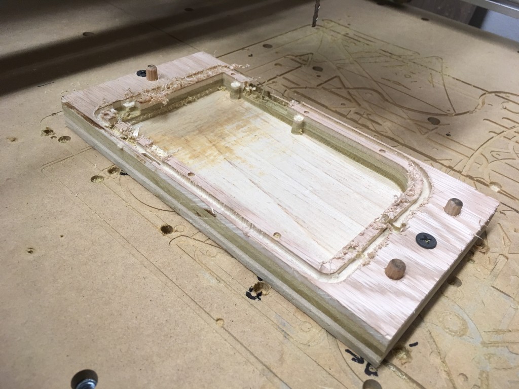
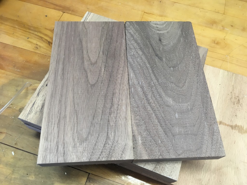
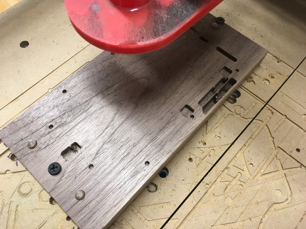
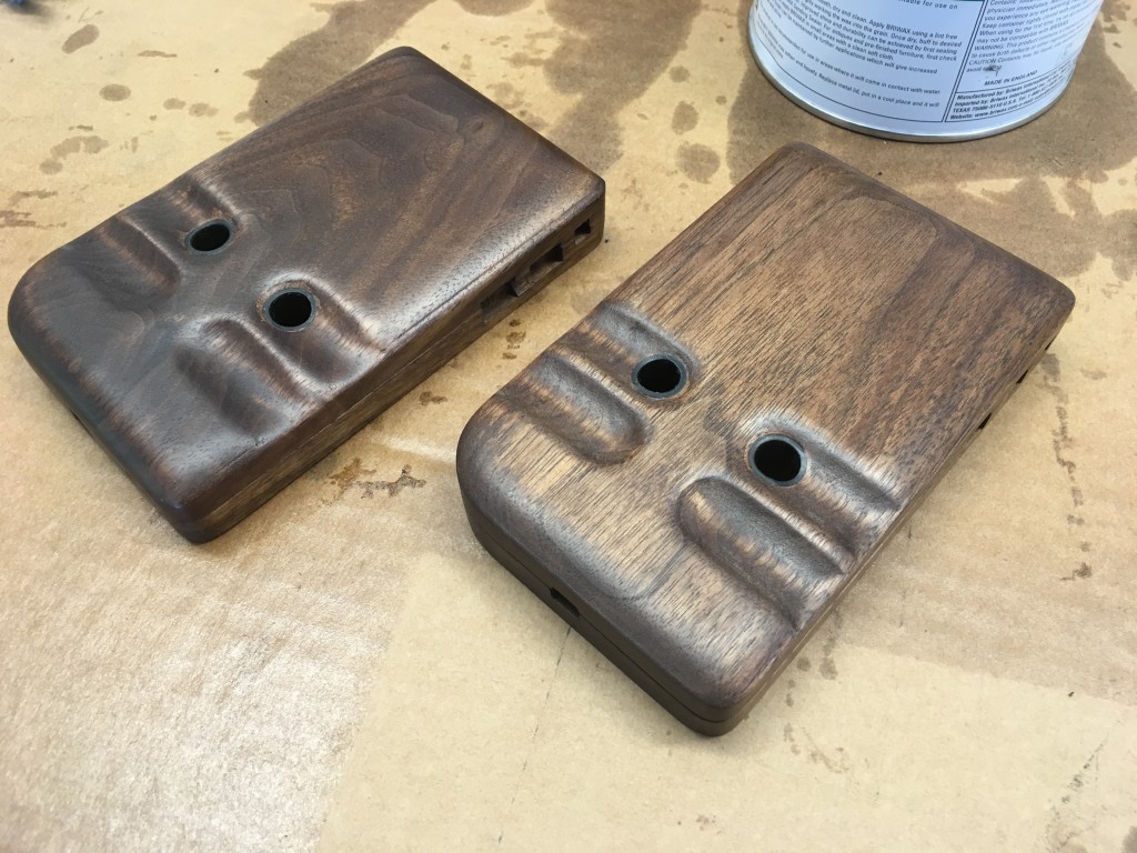
For the final version I used 3/4″ x 4″ American Walnut hardwood that I picked up from a local WoodCraft store. I told the employee there what I planned to with the wood and for some reason I don’t think he believed me. I bought a 4′ board and trimmed it into 8″ sections to machine. I tried to match the grain as much as possible so the halves would match.
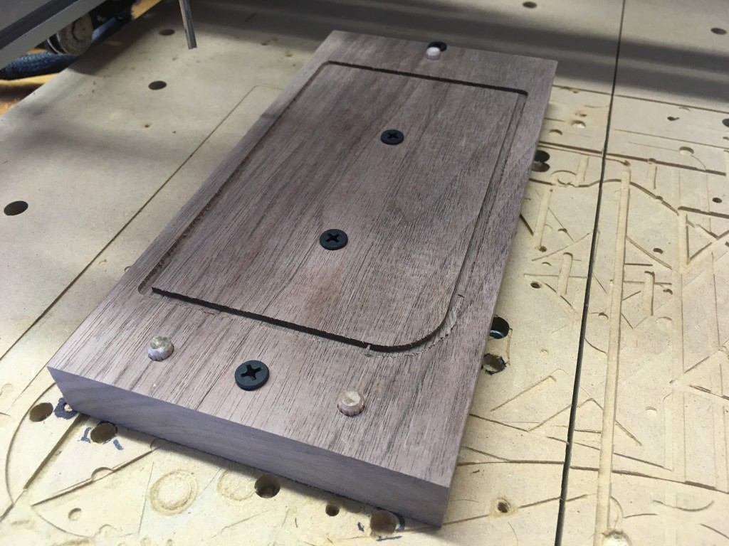
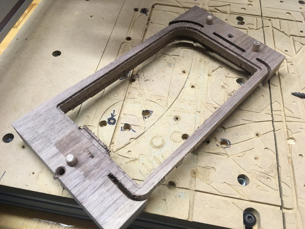
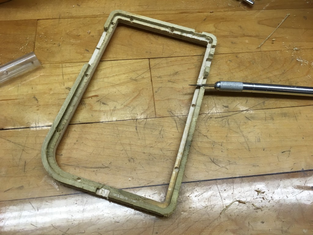
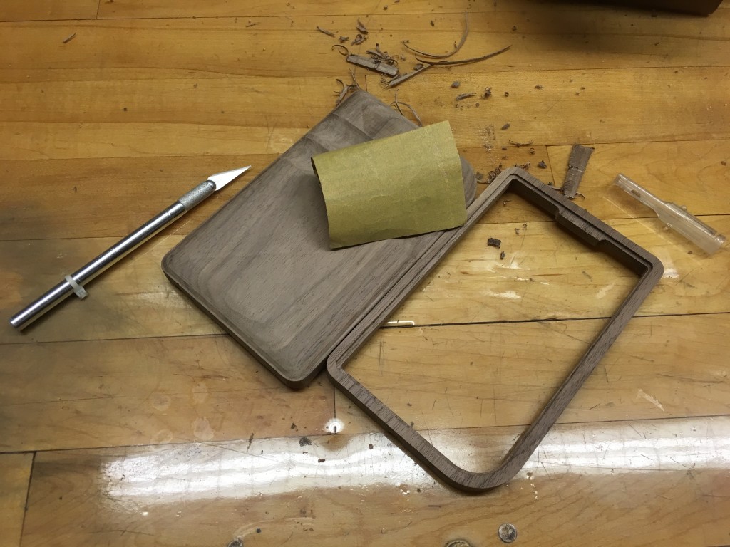
For the top part of the shell I used a 1/8″ straight double-flute bit to minimize tear out. Once cut, I used sand paper to get rid of the flashing then cut through the tabs with a band saw. An X-Acto knife was then used to trim away any excess material.
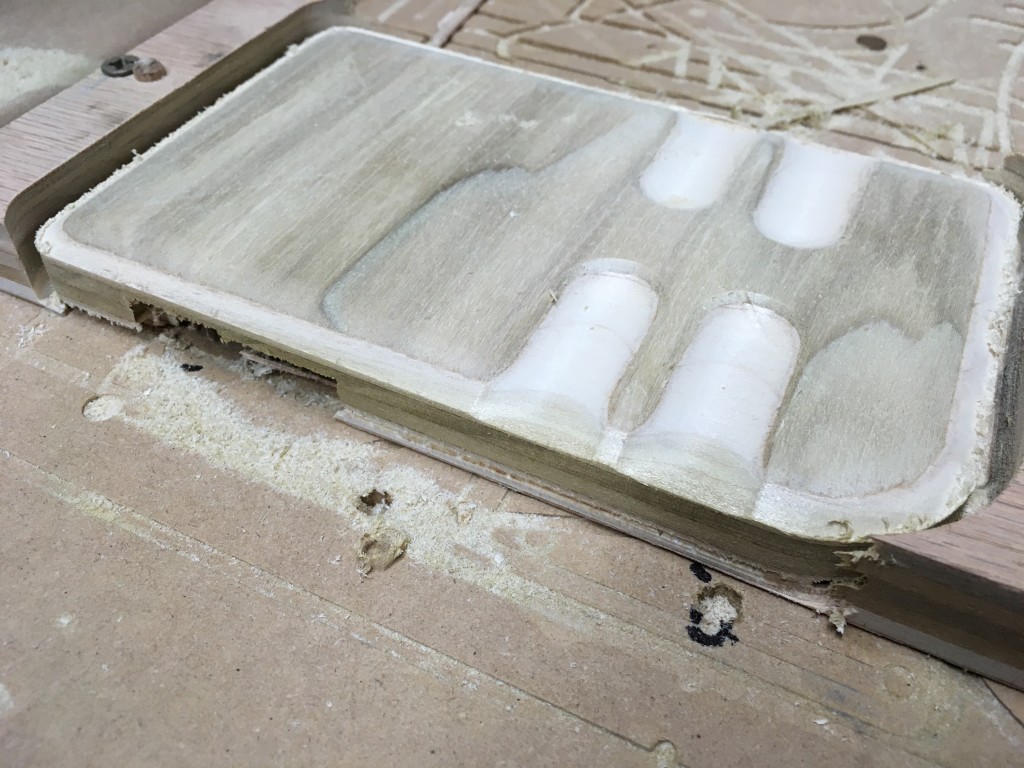
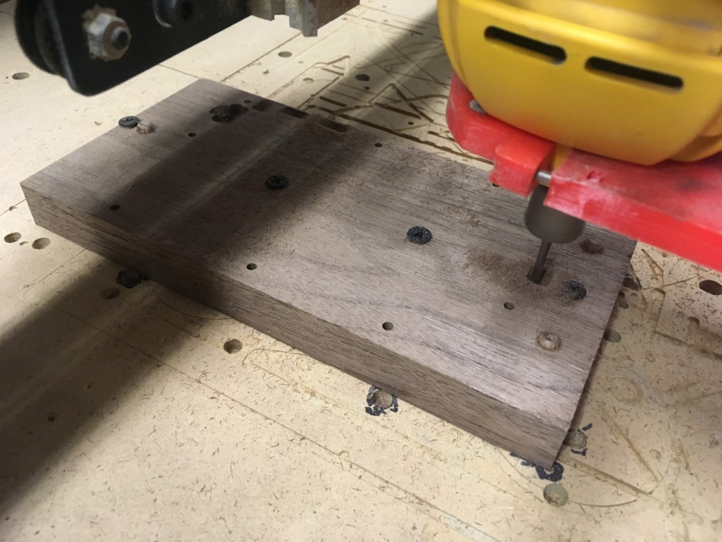
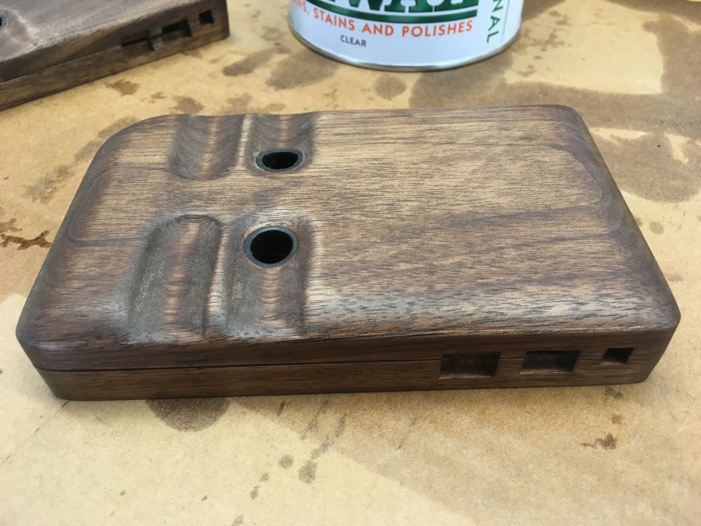
For the back I used a 1/8″ ball nose bit. I decided to forgo using a clearance bit as bit changes on a machine without homing switches will likely throw it off. The entire back was done as a finishing pass and after removing the sawdust it was shiny!
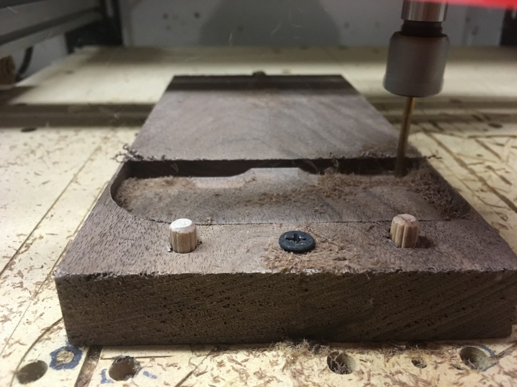
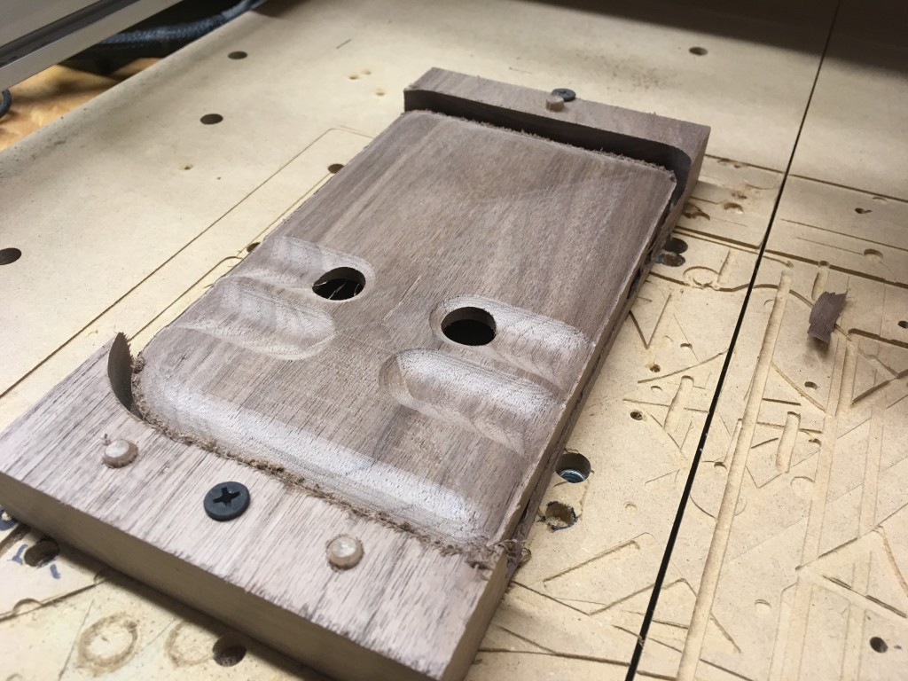
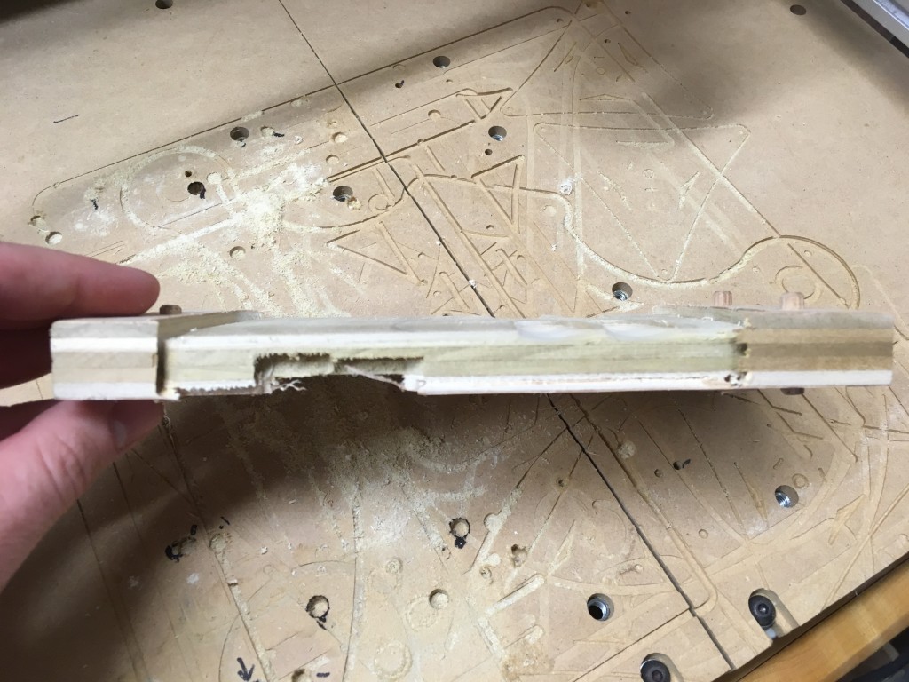
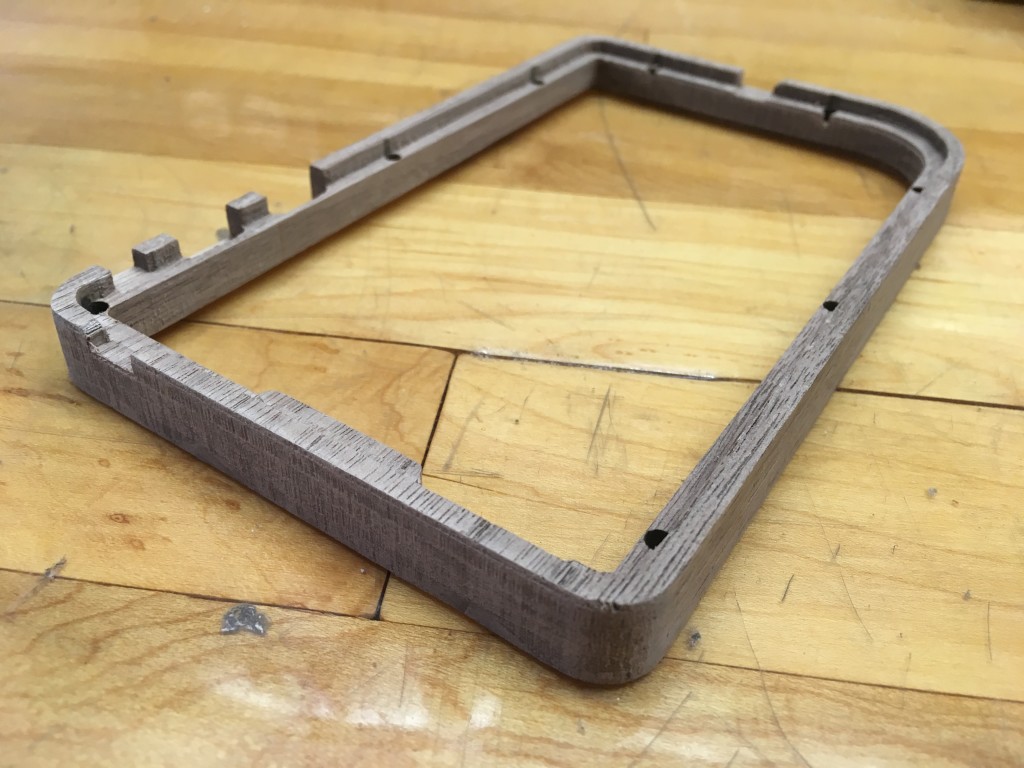
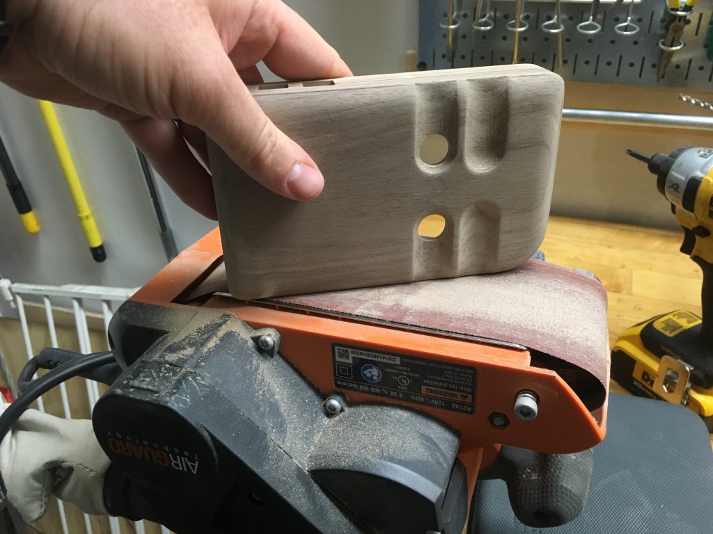
Cutting is always followed by a lot of sanding. I trued up the edges (they were slightly off as with any of my multi-sided machining operations) by mating the halves together and mounting my belt sander in a vise then sanding until the assembly was smooth.
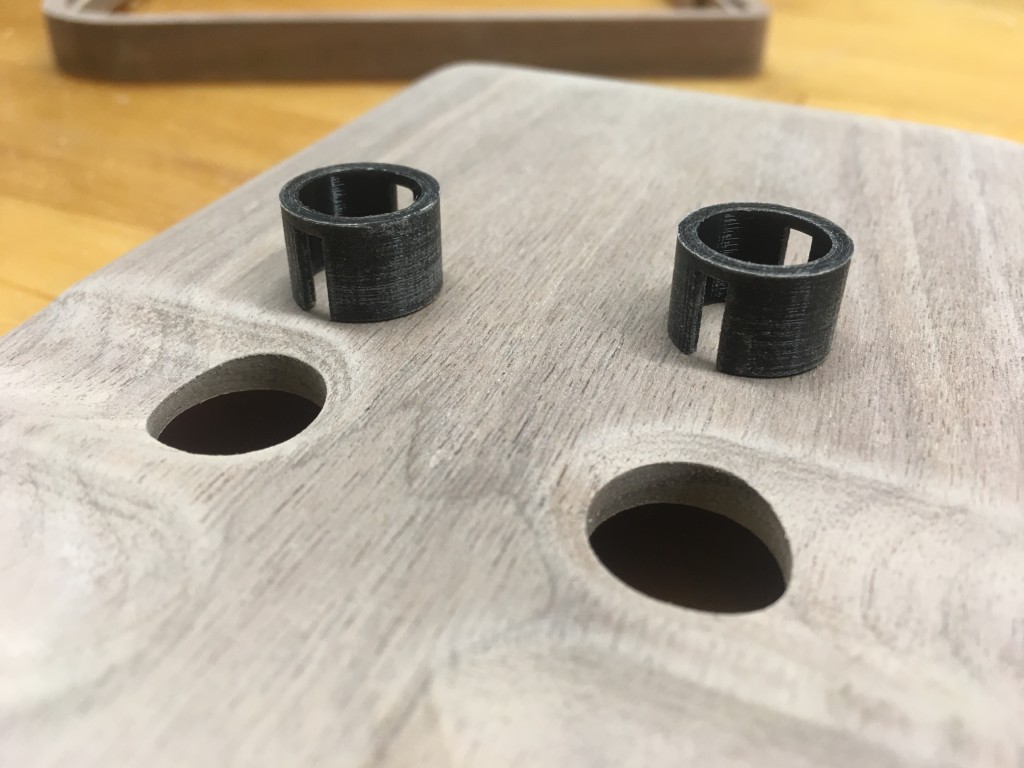
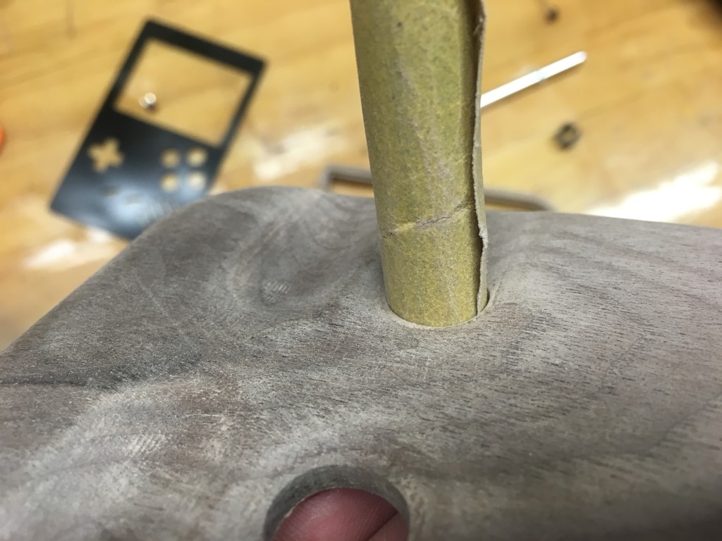
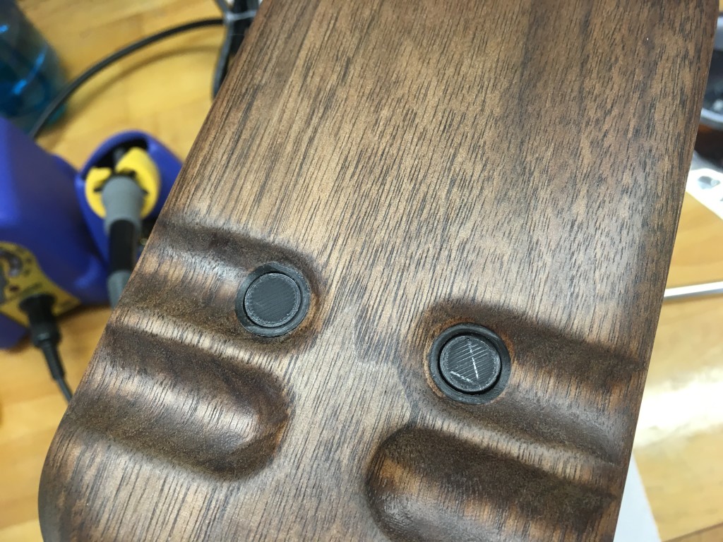
I also installed the button wells for the back-side buttons. The 3D printed parts were lightly sanded and the hole was slowly enlarged with sandpaper until the well was gently held in place by friction. Then I applied CA glue and positioned the top of the well flush with the finger indent. Once the glue set I used a Dremel sanding drum to contour the well with the finger indent and hand sanded the whole thing to ensure there were no sharp edges.
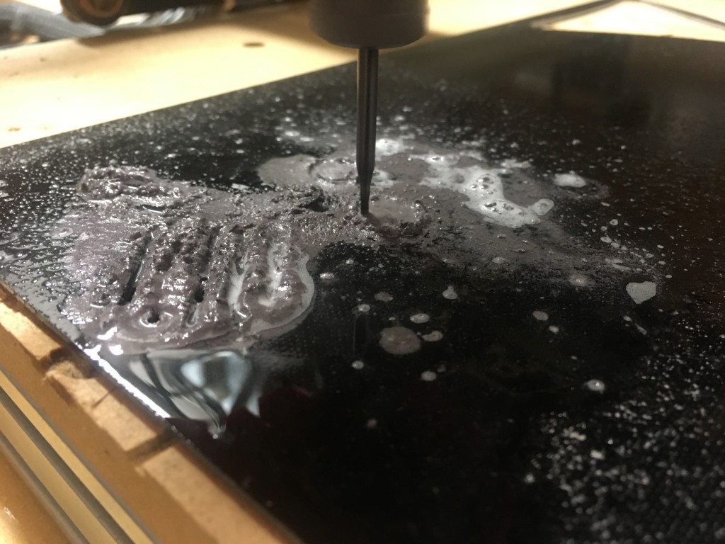
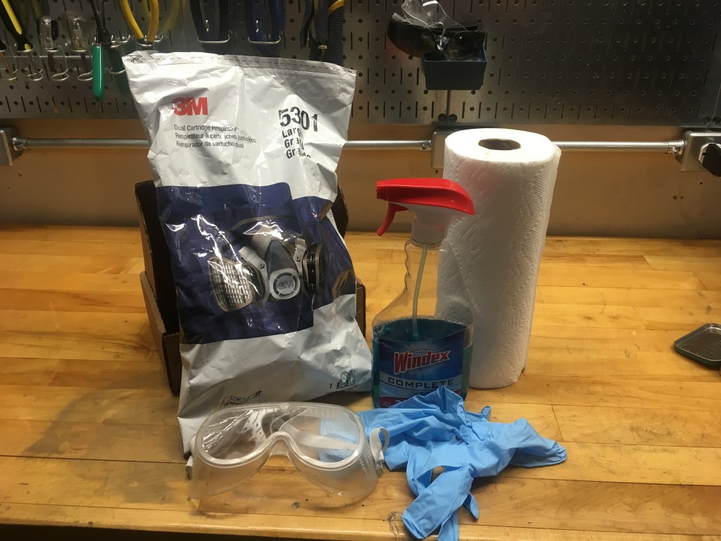
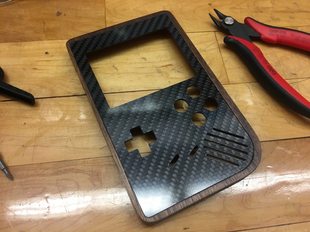
Next I started on the carbon fiber. I love working with this stuff but you do need to be very careful when you machine it. The dust is extremely bad for your lungs and it’s conductive so it can wreck havoc on your machine. My solution for this is to wet the work piece with Windex before and during machining so the dust forms a slurry instead of going into the air. The slurry can then be wiped away and disposed of. Make sure you wear a good respirator, googles, and gloves anyway as an additional precaution. To hold the carbon fiber on the machine bed I’m using carpet tape. It holds strong but can be removed cleanly with little or no residue (just don’t machine into it much or it will gum up your bit.)
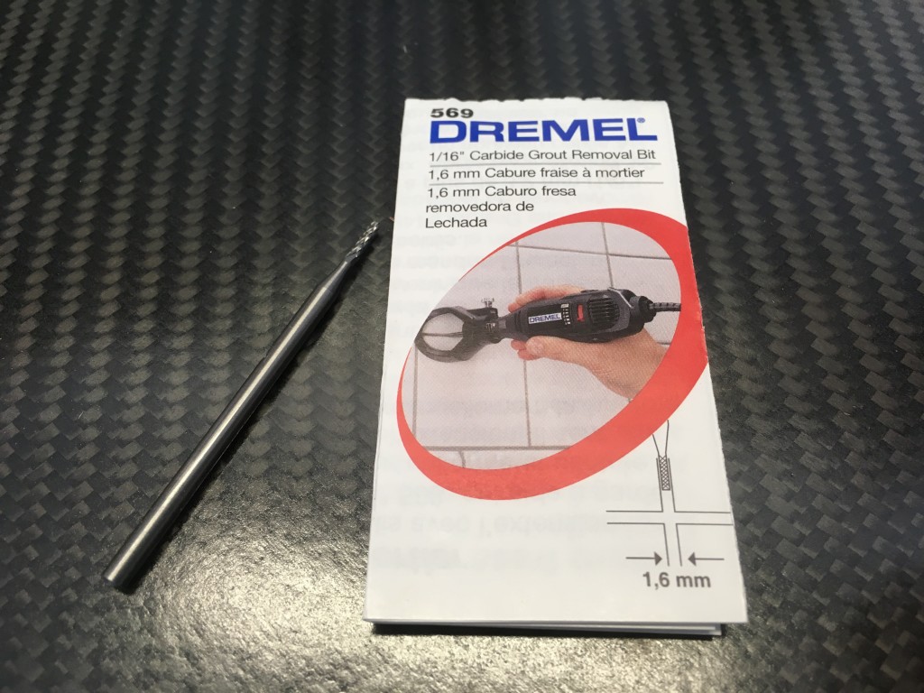
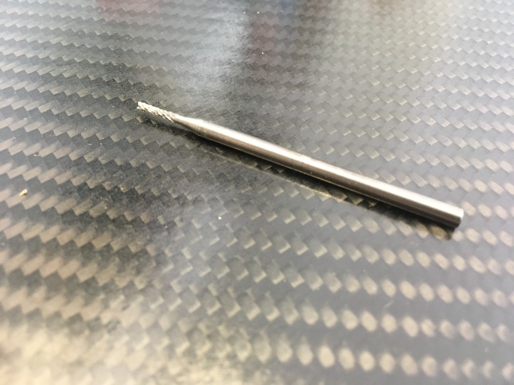
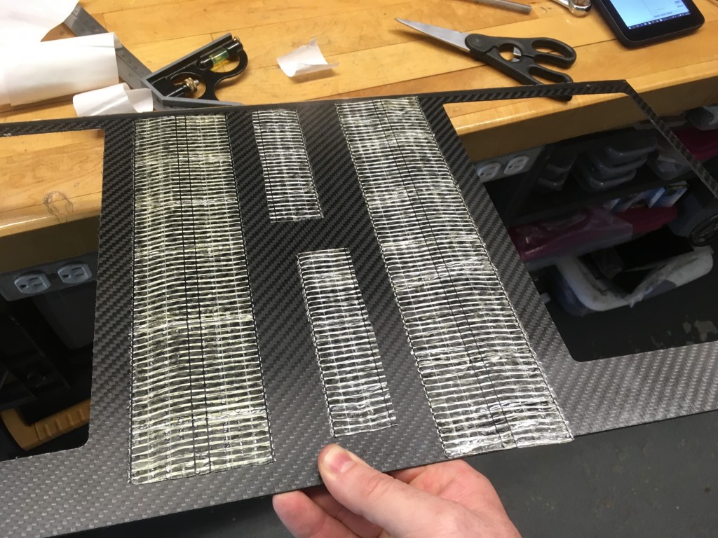
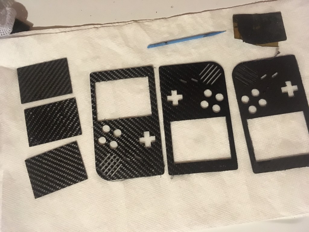
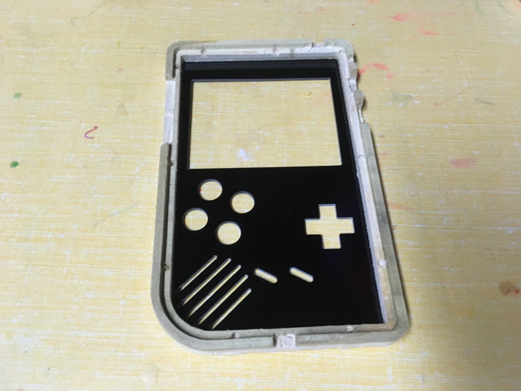
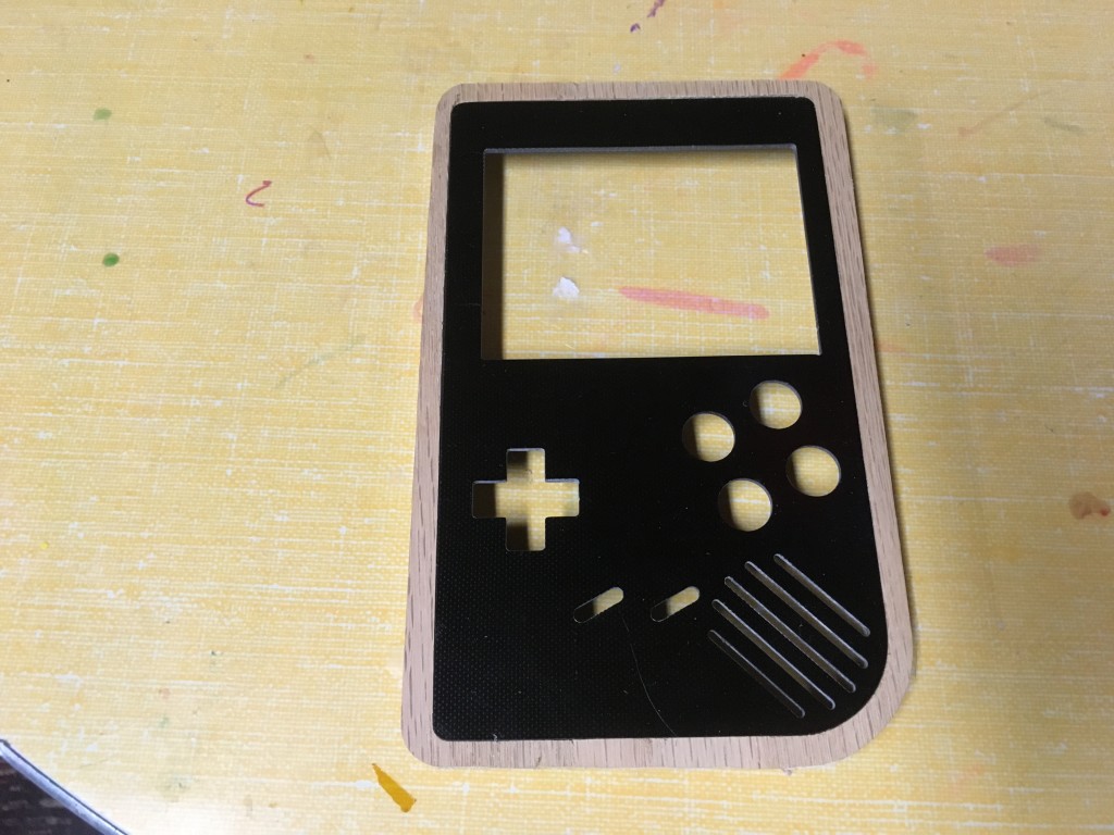
An additional tip for cutting carbon fiber; you don’t need a fancy bit! I use a Dremel #569 1/16″ “Grout Removal” bit that you can pick up at your local big box store for around $10. They are solid carbide and have a “chip-breaker” design that stays sharp for a long time. I’ve cut lots of carbon fiber and have owned 3 of these bits total, and all still cut! Once the parts were cut out, I wet sanded the edges under running water to make sure there are not sharp edges. For tight corners I used a sanding pen that I picked up at a local hobby store (basically a piece of plastic with embedded abrasives.)
ELECTRONICS
I’m not going to go into too many details on the electronics side of things because Giles (aka Kite) has done such a great job documenting the assembly and testing procedures for the SAIO board. I’ll post the links to his store and instructions at the bottom of this post.
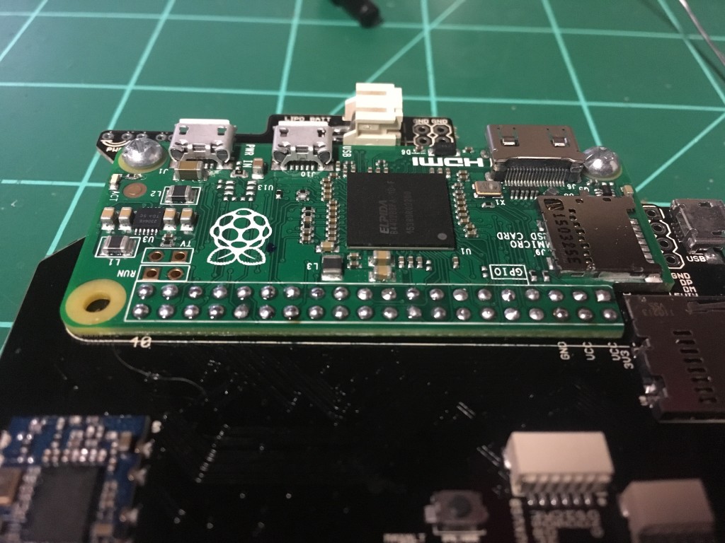
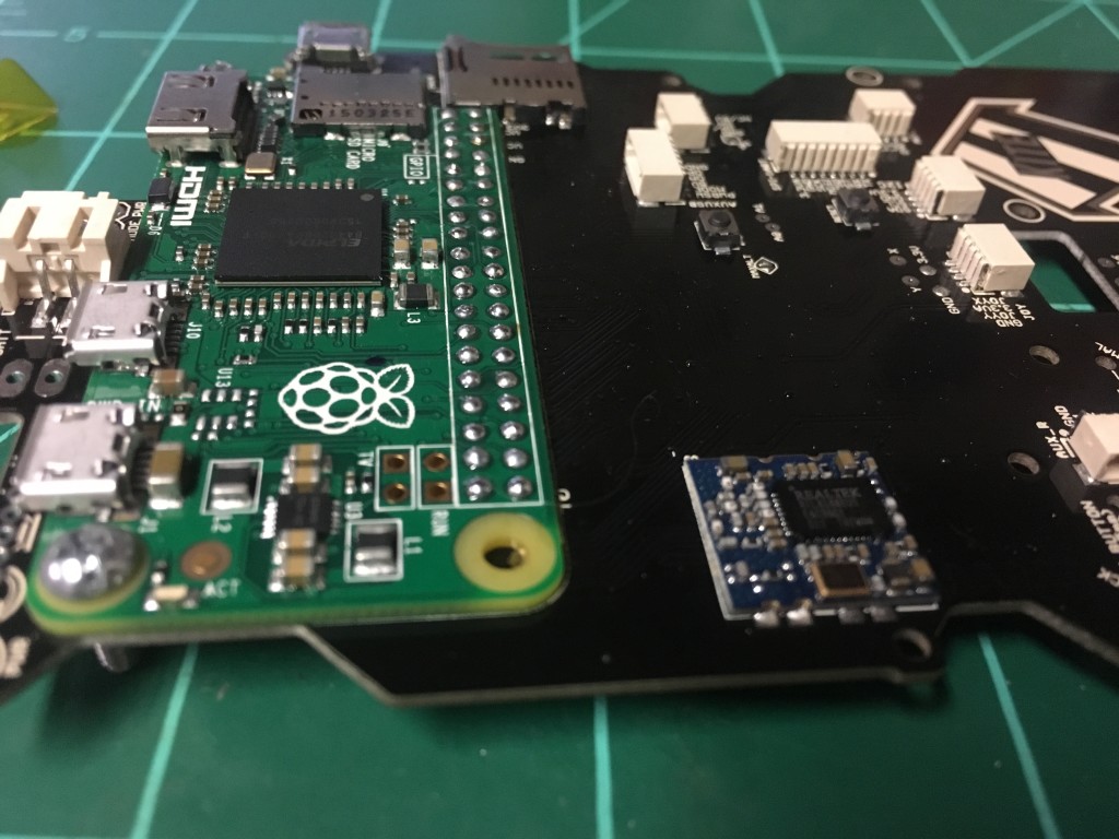
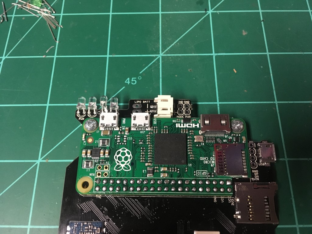
The version I used is an earlier one that involves surface-soldering the Pi Zero onto the SAIO PCB. Later versions have header pins that makes things a lot easier. There’s even a brand-new version called the “Circuit Sword” that’s solder free and uses the Raspberry Pi Compute Module 3 (CM3) that has about 10x the horsepower as the Pi Zero. If I hadn’t already purchased these that’s the one I’d be using. (If you’re using one of the CM3 versions it *should* fit this case. If it doesn’t, send me one and I’ll update it 🙂 )
TESTING
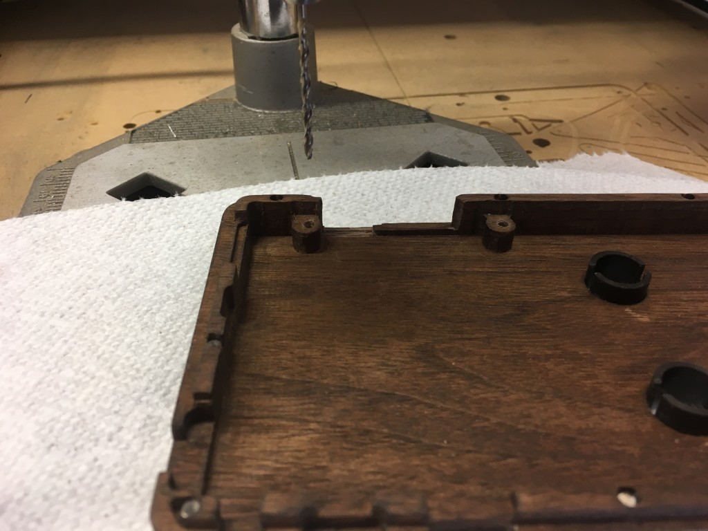
If you’re building one of these yourself, test fit EVERYTHING right now. Put the PCBs in place and trim out any additional clearance with a hobby knife. Use a drill-press to drill the holes for the volume control / USB port board. Boot your electronics to make sure everything works before you install it into the enclosure. While you *can* do some trimming once the case is finished it’s much easier to do it now. I didn’t test absolutely everything and ended up needing to touch up later. Learn from my mistakes!
FINISHING
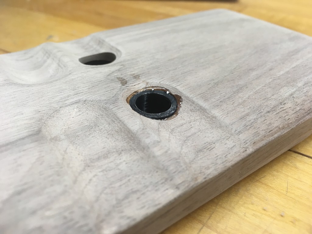
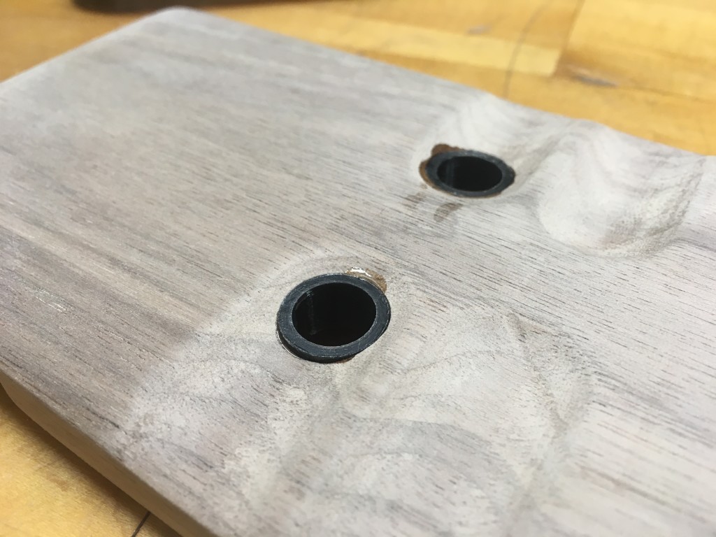
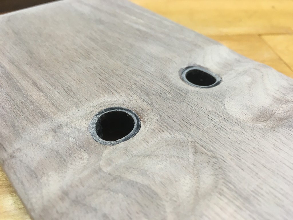
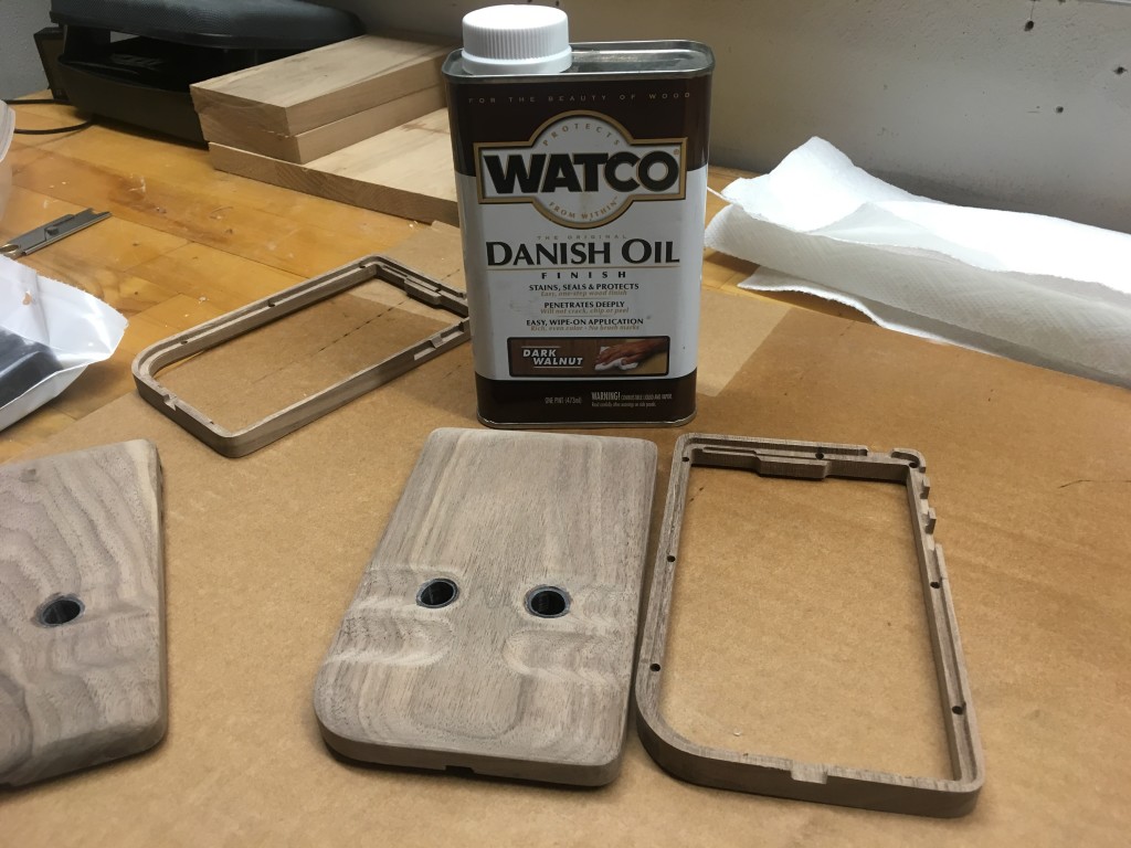
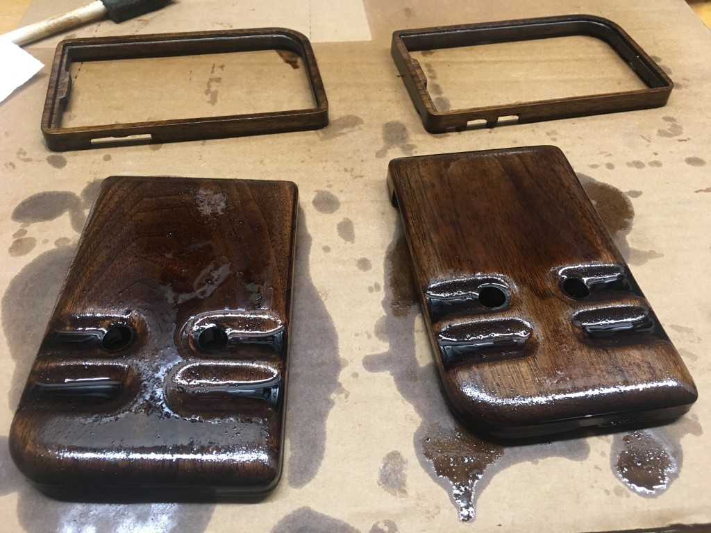
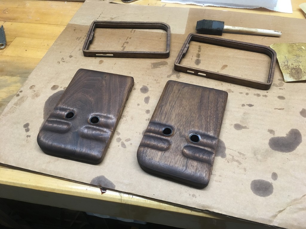
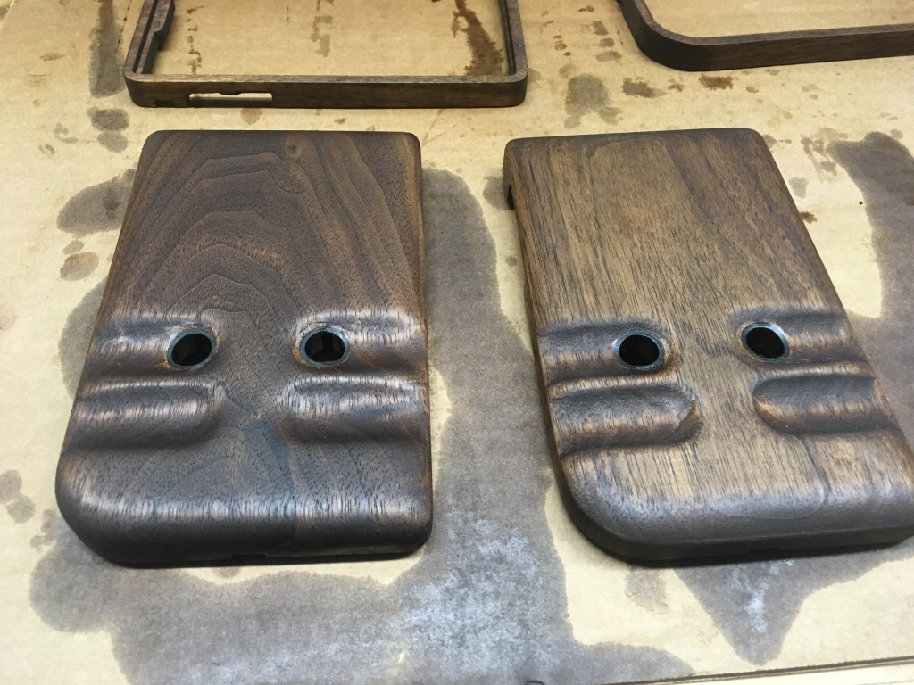
For the finish, I wanted the wood to be smooth but not slippery so that it was less likely to get dropped. Ideally I wanted to feel the wood grain and be pleasant to hold for extended periods of time. For the stain I chose Watco Danish Oil – Dark Walnut which is a stain / varnish in one. It was applied with a rag and quickly soaked into the wood. Once it sat for around 15min or so I wiped off the remaining stain and found the color to be perfect. I attempted to wet sand the wood with the stain in hopes that the dust would act as a wood filler but it didn’t work (and I wouldn’t recommend it.)
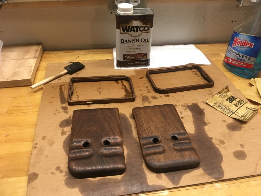
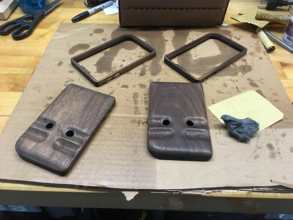
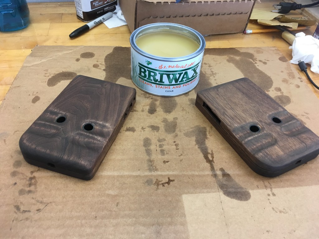
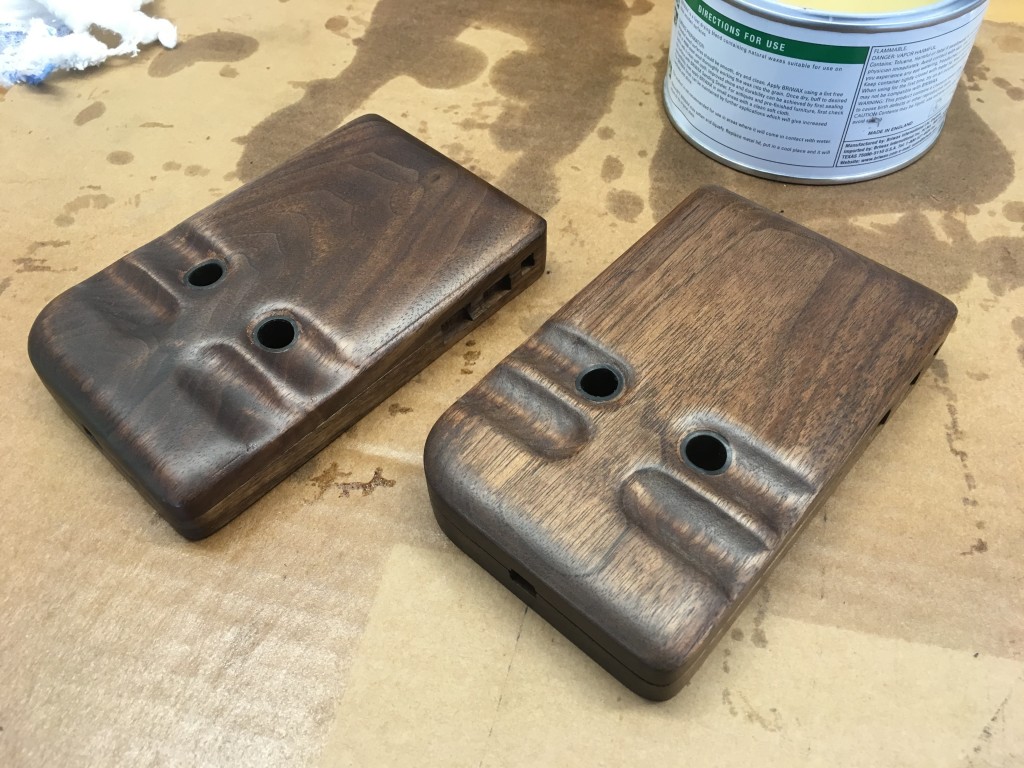
Once the stain dried I applied 4 coats of Briwax furniture wax. It reminded me a lot of car wax (and the application process is the same) but is made for wood. Wax on, wax off. The results were exactly like I wanted. The finish was slightly glossy and delightful to touch. Pictures don’t do it justice.
ASSEMBLY
Fortunately you already assembled and tested everything before you put the finish on your enclosure, right? If you didn’t (like I may not have) it’s not the end of the world. If you need to do any more carving to get the perfect fit you still can – just touch up using a cotton swab.
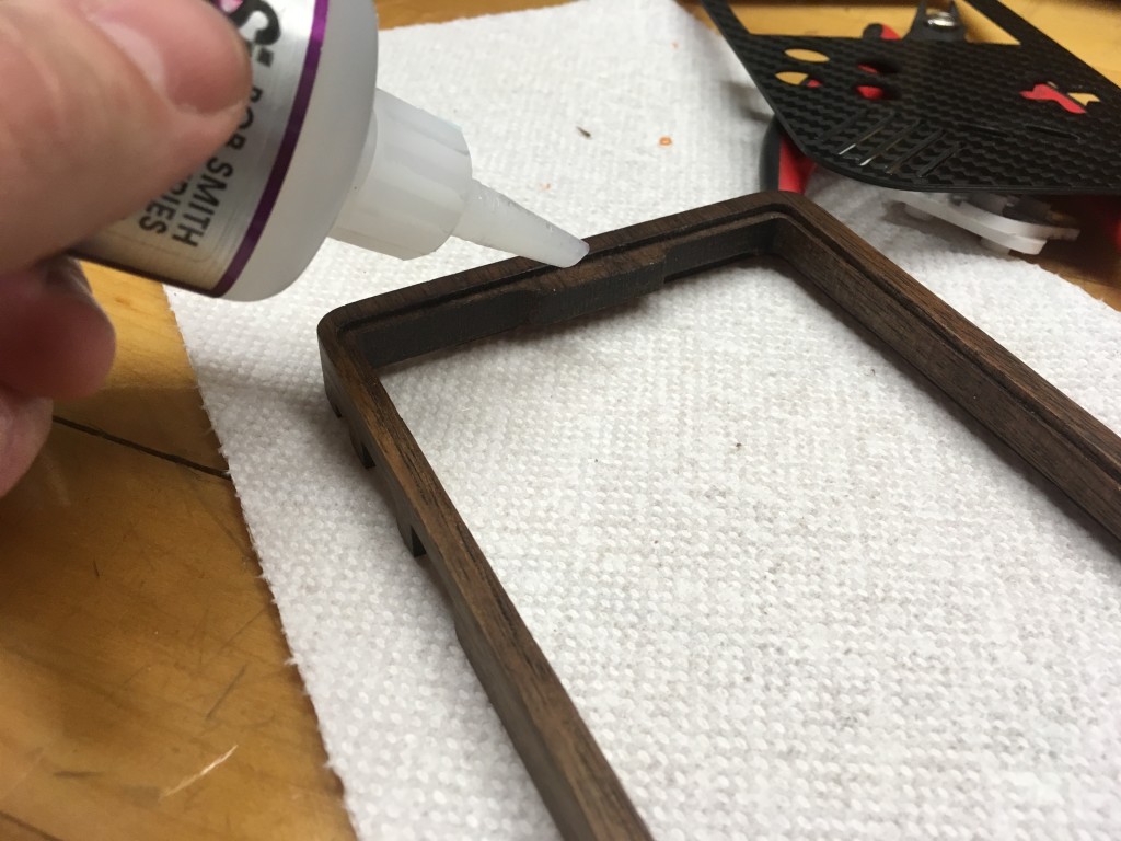
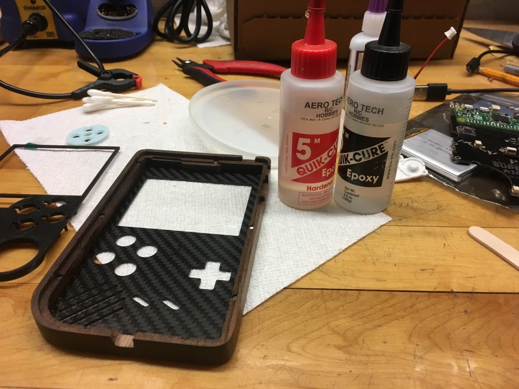
First I glued the carbon fiber front into the top of the enclosure using a thin bead of medium CA glue. Excess CA was carefully removed from the carbon fiber with a cotton swab dipped in acetone (try not to get any CA on the wood or your fingers.)
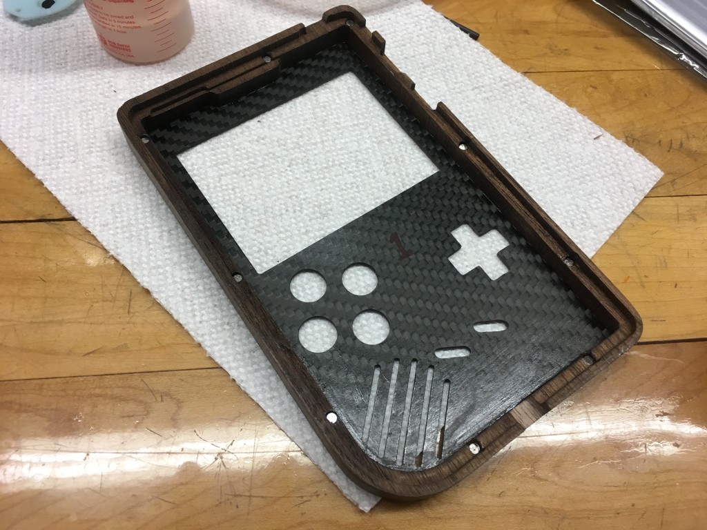
Next, I installed the 3D printed insert onto the back of the top-plate. The insert was trimmed with a knife and the button wells were lightly sanded until smooth. To affix the insert to the carbon fiber I used 5min epoxy so I could re-position it to make sure the buttons didn’t bind. My process was to put a very sparing amount of epoxy on the back of the insert (carefully avoiding areas where the epoxy might get into the button wells) and placing it gently onto the top-plate. Then, while holding the case, I dropped in all the buttons and (direction, X, Y, A, B, start & select) and pushed each one to make sure there was no binding. If binding was felt I re-positioned the insert and tested the buttons again. If you’re doing this yourself and the epoxy sets before you’re ready, you should be able to use your knife or some rolled sandpaper to fix any remaining binding.
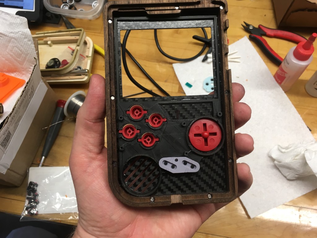
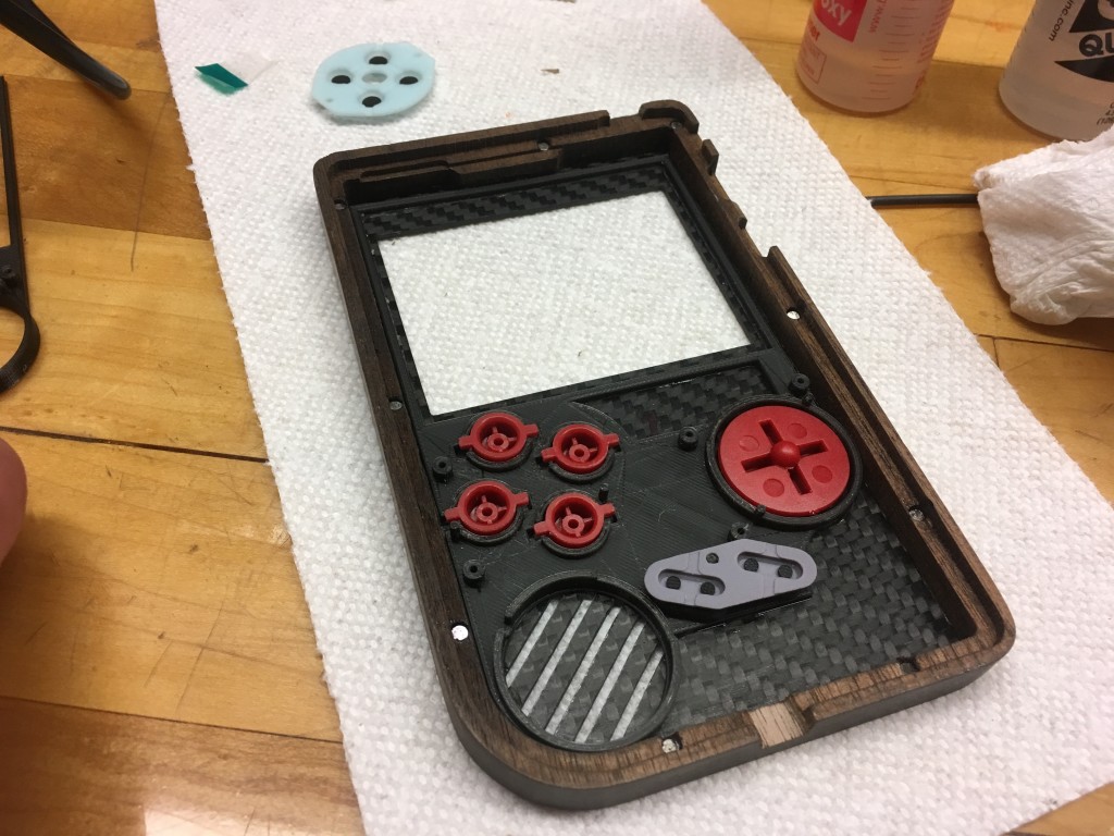
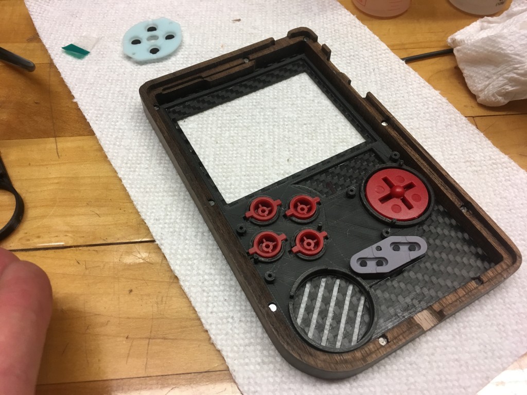
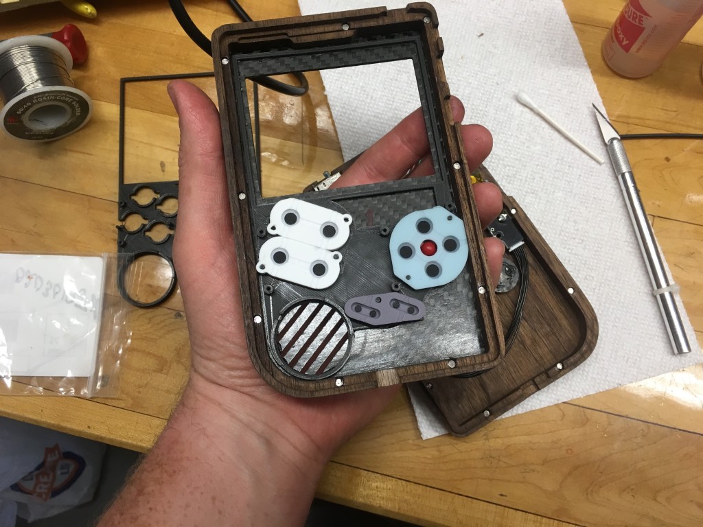
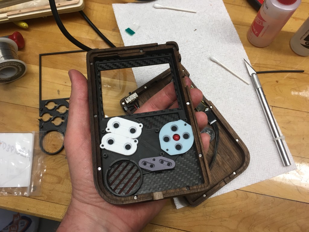
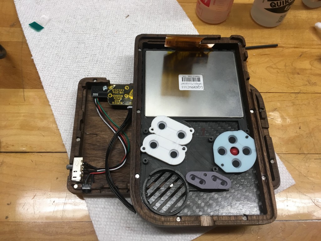
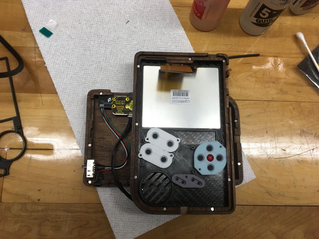
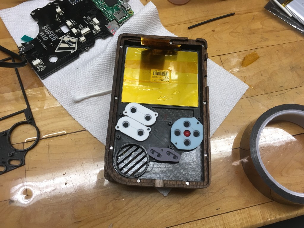
I also lightly sanded the bottom edges of the buttons to make sure they don’t catch on the layers of the insert. After the epoxy set I dropped in all the buttons and installed the rubber membranes. All of the membranes except the X and Y buttons fit onto the pegs of the insert. The X and Y membrane just sits on top of the insert then gets sandwiched in place by the PCB. Next, the screen was installed with the ribbon cable closest to the TOP of the enclosure. I secured the screen by placing 4 dabs of hot glue on the corners. I also added some Kapton tape to the back of my screen to reduce the risk of shorts (you could use any non-conductive backing like packaging tape, contact paper, etc.) At this time I also installed the magnets. I marked the polarity with a Sharpie, put a dab of CA on the back, and used a pencil to put the magnets into place.
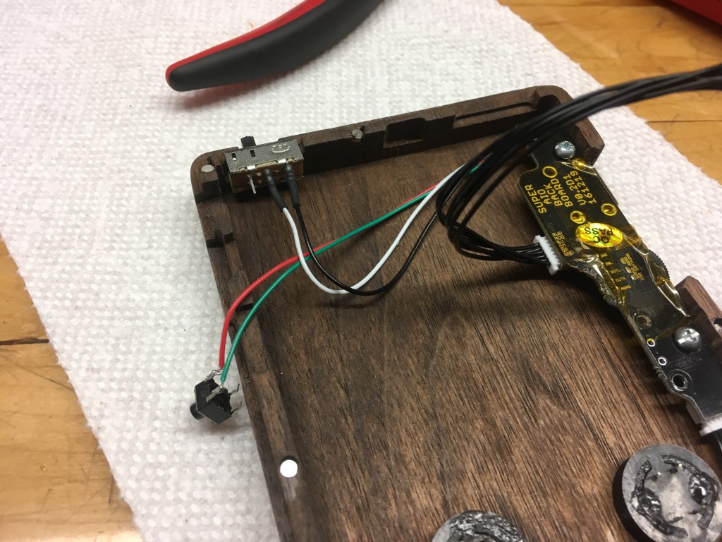
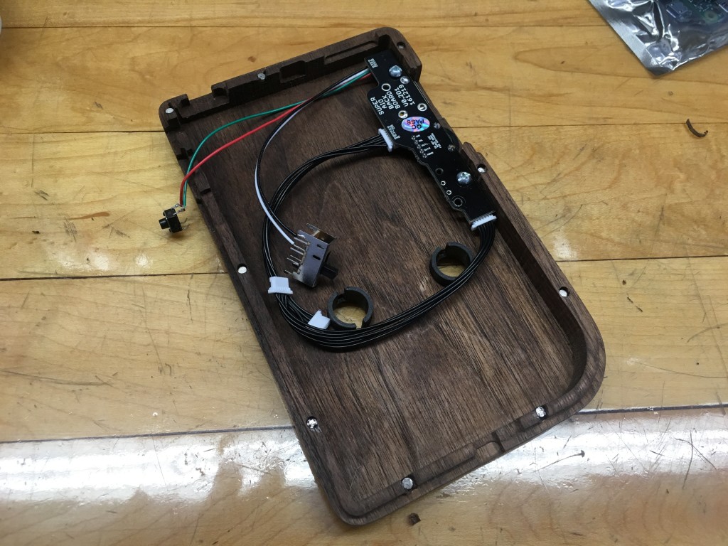
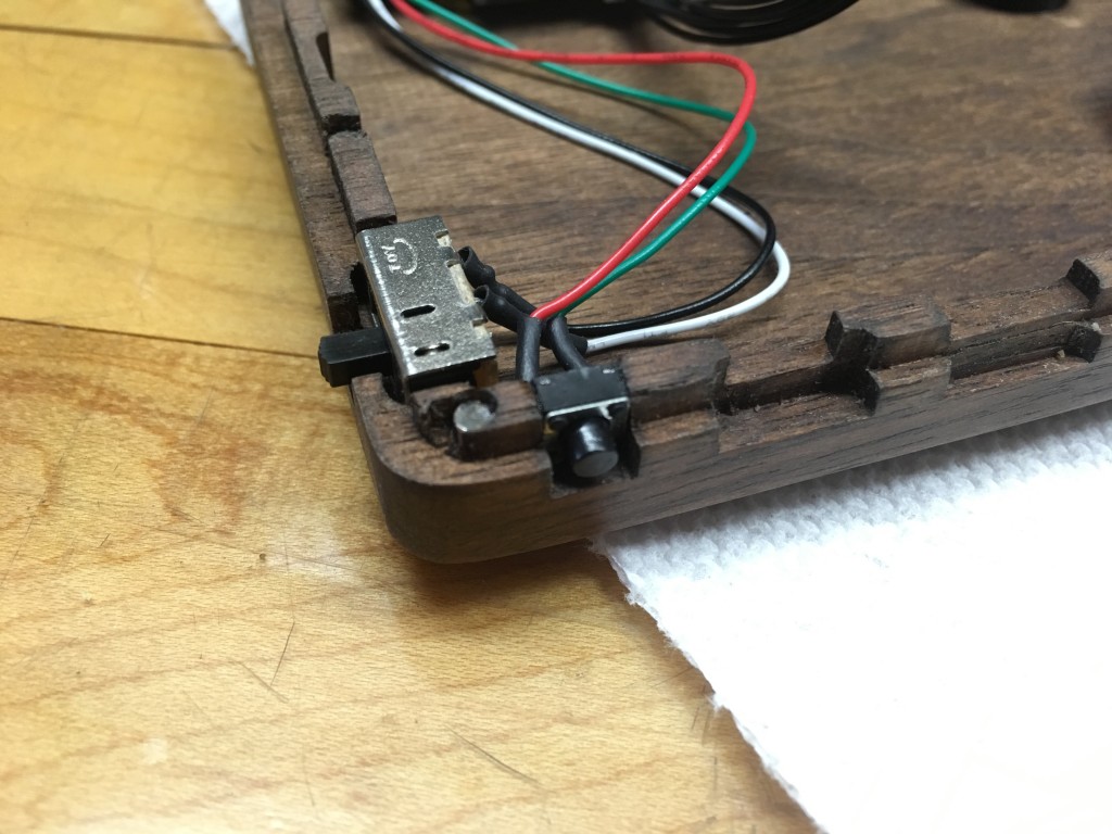
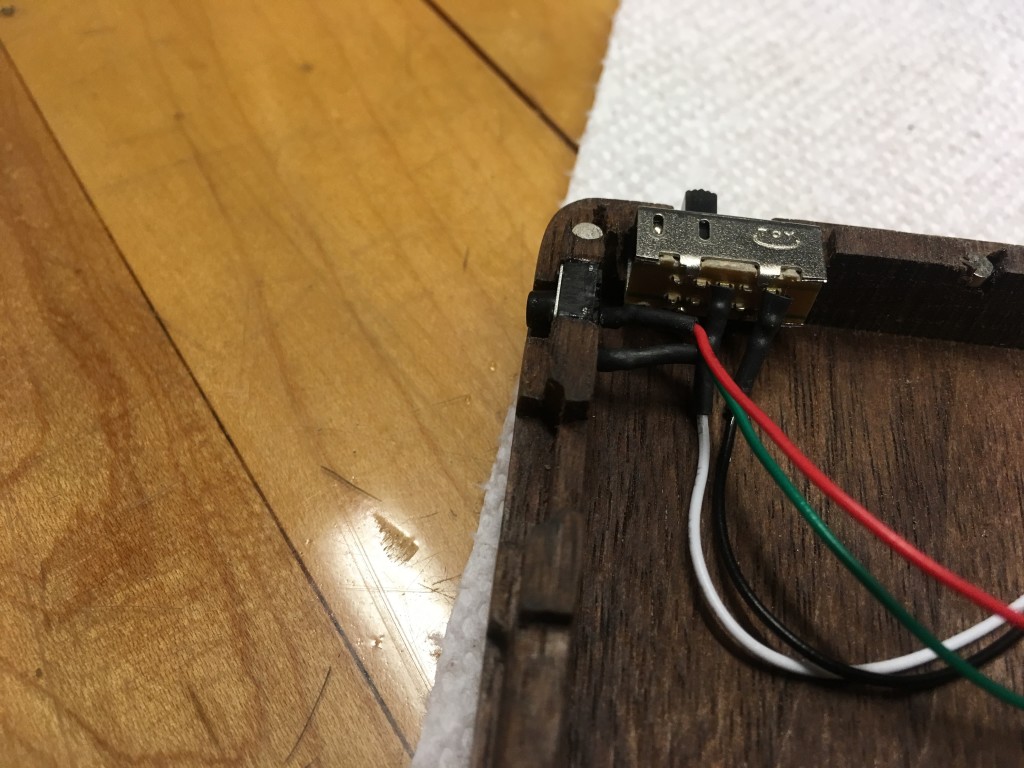
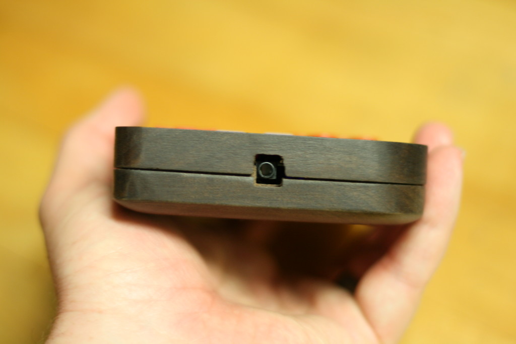
I now installed the “back board” PCB which has the volume control and USB port. The PCB was screwed into the protrusions left from machining. I found that 3/16″ 4-40 hardware worked well for this. The power switch and mode button were held in place with another dab of CA glue.
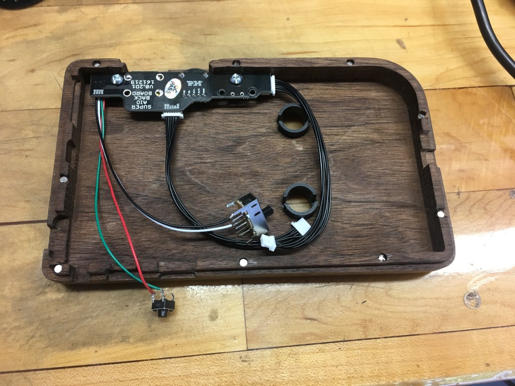
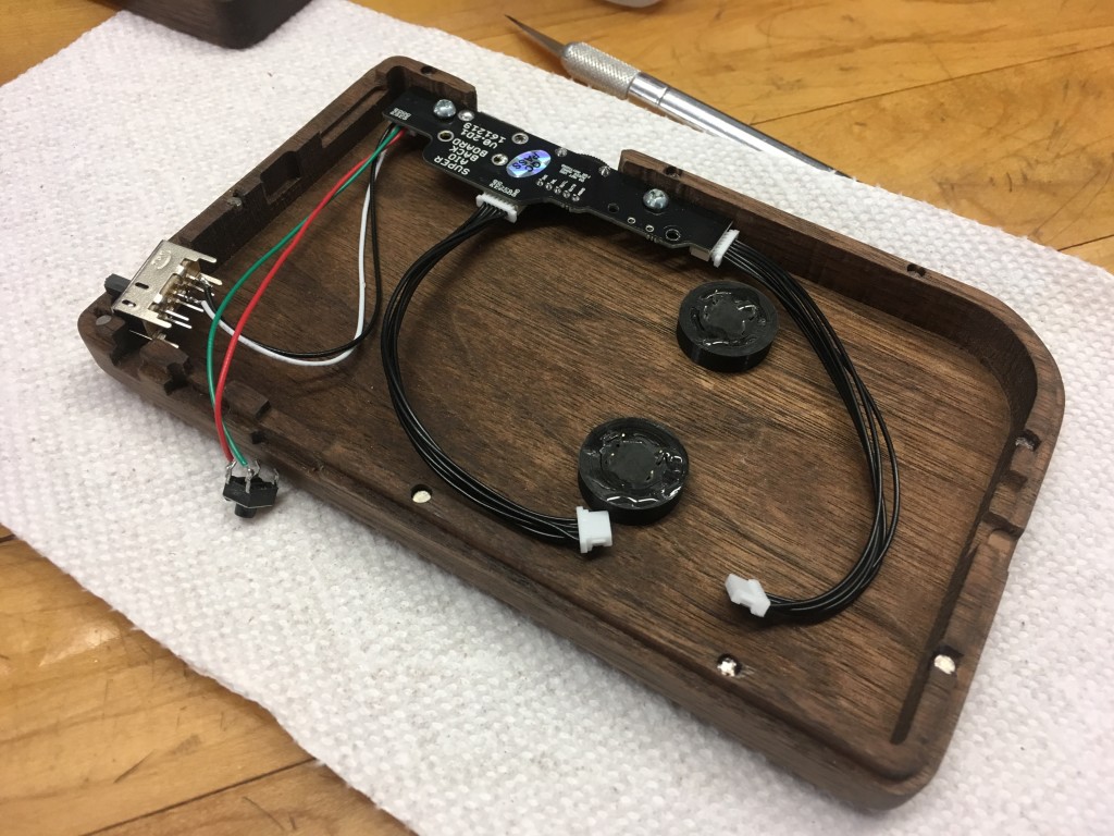
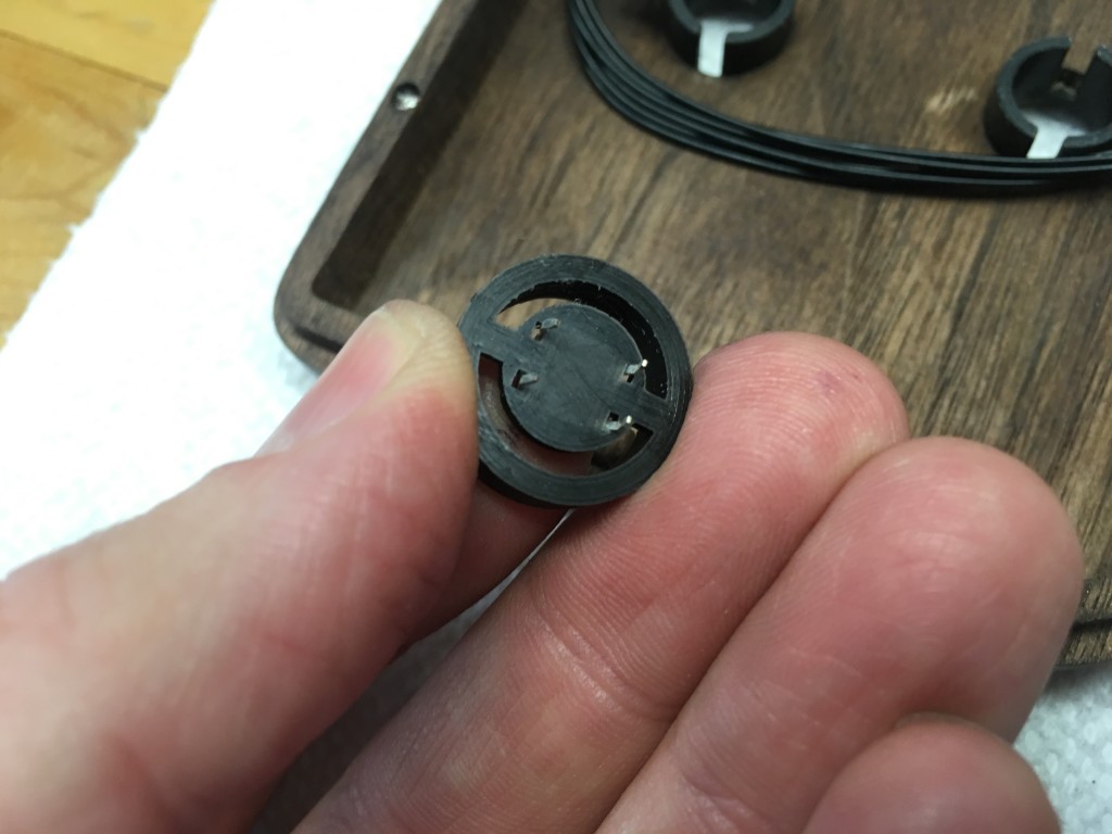
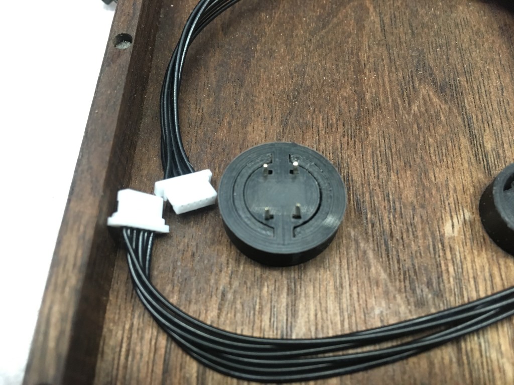
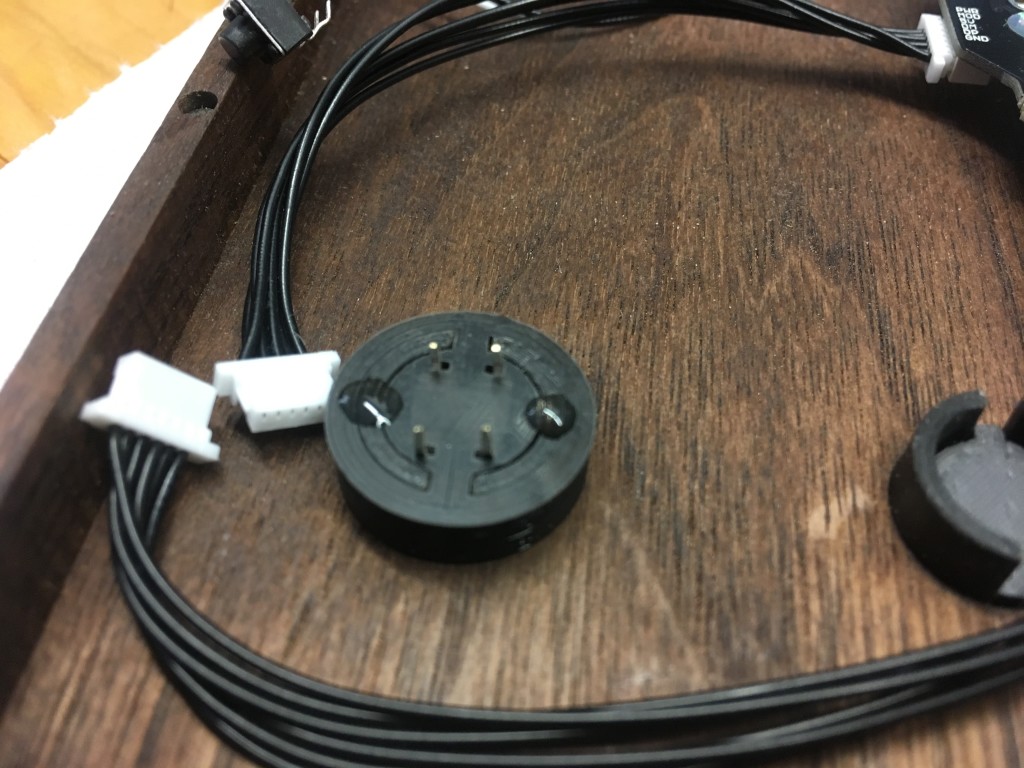
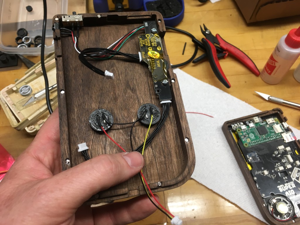
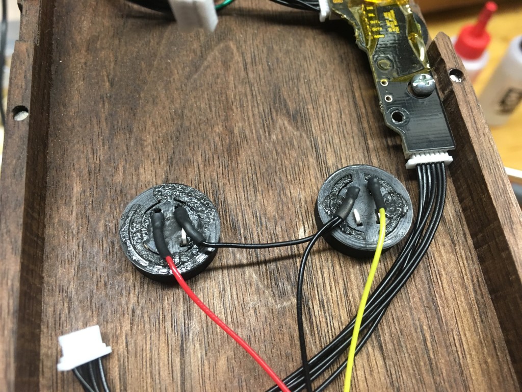
The back buttons were installed next. The buttons went together by pushing the tactile switch into place on the backing (the legs may need to be bend slightly) and dropping the button into the well (ears up of course.) The backing was then pushed into place making sure there was no excessive play while taking care to make sure the button wasn’t pre-pressed. Once I was happy with the action I used a few dabs of CA to hold everything in place. The buttons were wired according to the SAIO instructions and all connections were covered with heat shrink.
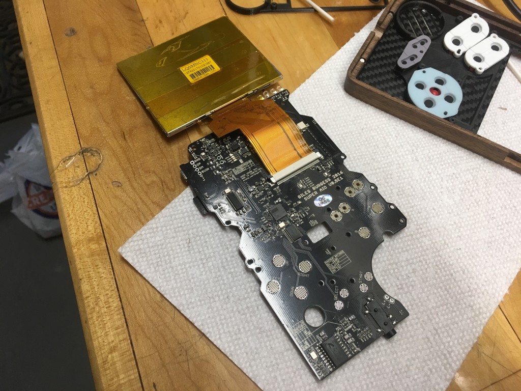
The SAIO PCB was then installed. First, I connected the ribbon cable from the LCD screen to the to the FPC connector on the SAIO board. Care was taken when doing this to make sure I 1) don’t put any stress on the ribbon cable as it could shear and 2) was careful with the FPC connector as it’s really fragile (I ended up breaking mine but by some miracle happened to have a spare.) Unfortunately I wasn’t able to take photos of that part since it was a two-hand job.
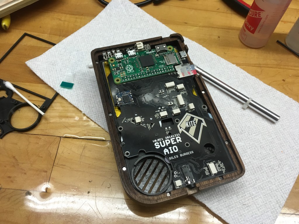
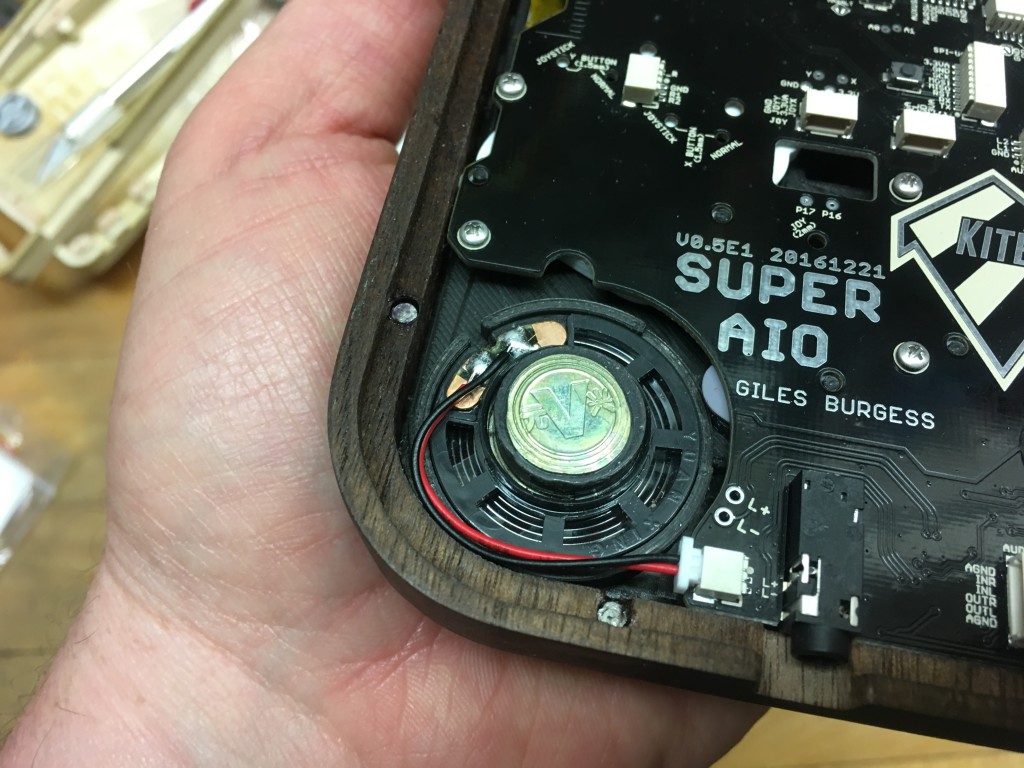
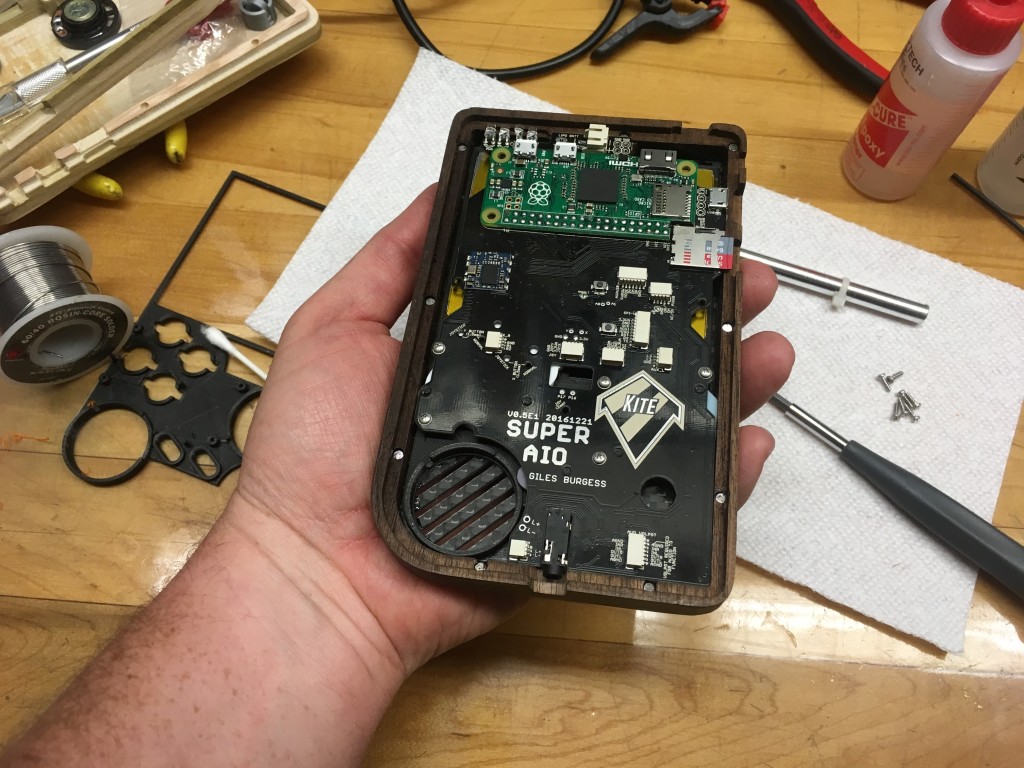
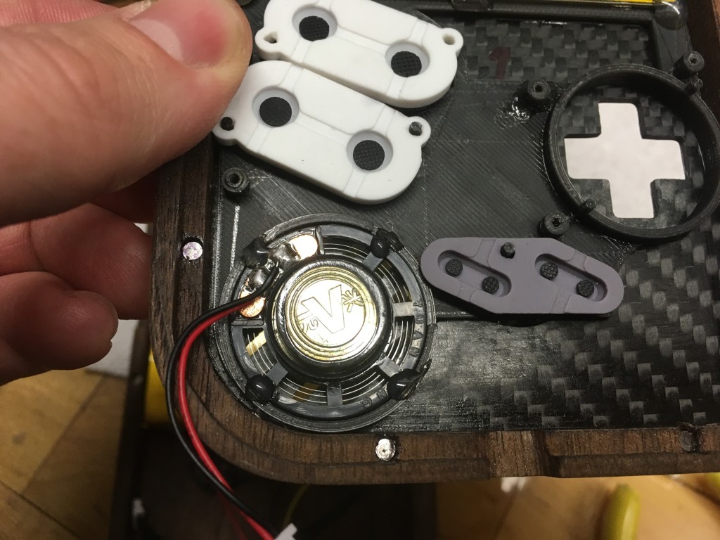
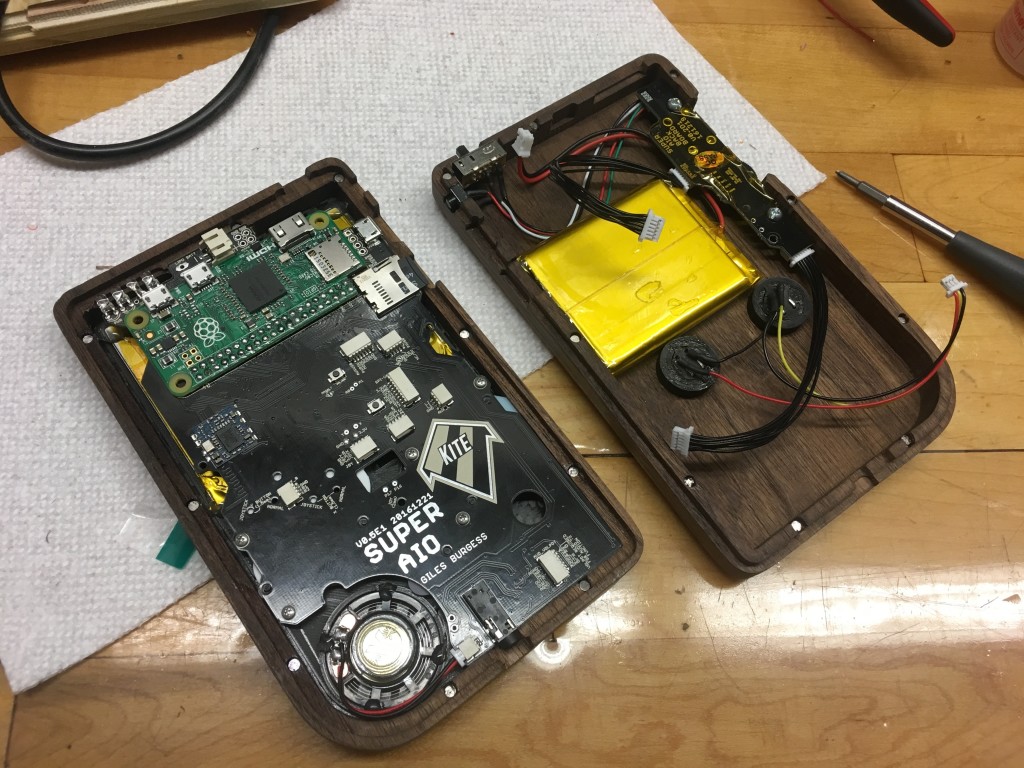
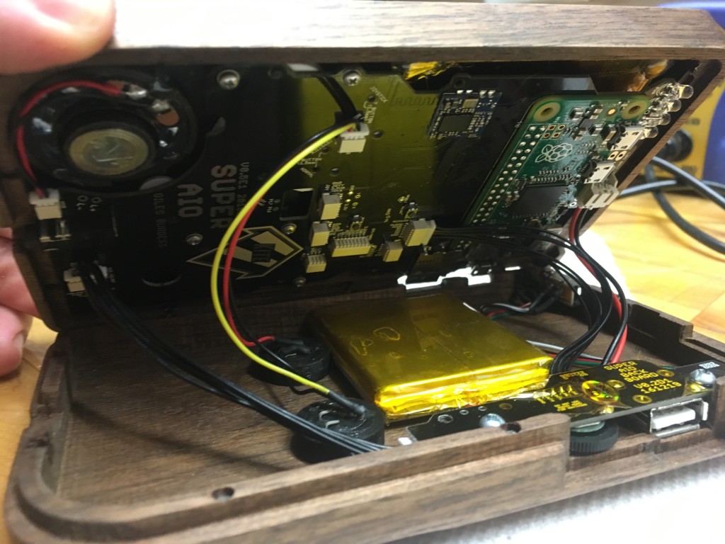
The SAIO board was moved into place on the 3D printed insert and popped onto the pegs. With the PCB in place the rubber membranes were sandwiched in, holding the buttons in place. Screws were then installed hold the SAIO board in place (screw holes are marked with a white circle.) I found that I had to “tap” the insert by tightening the screw a turn or two, backing it out slightly, and tightening it again until the screw was snug against the PCB. I did happen to break one post but used some CA to stick it back together. I put the speaker into place and held it there with a few dabs of hot-glue. The speaker wires were soldered and plugged in as per the SAIO instructions.
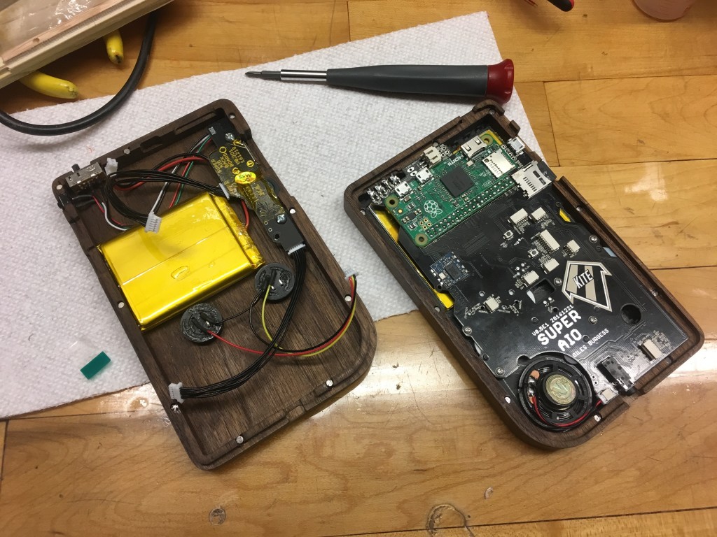
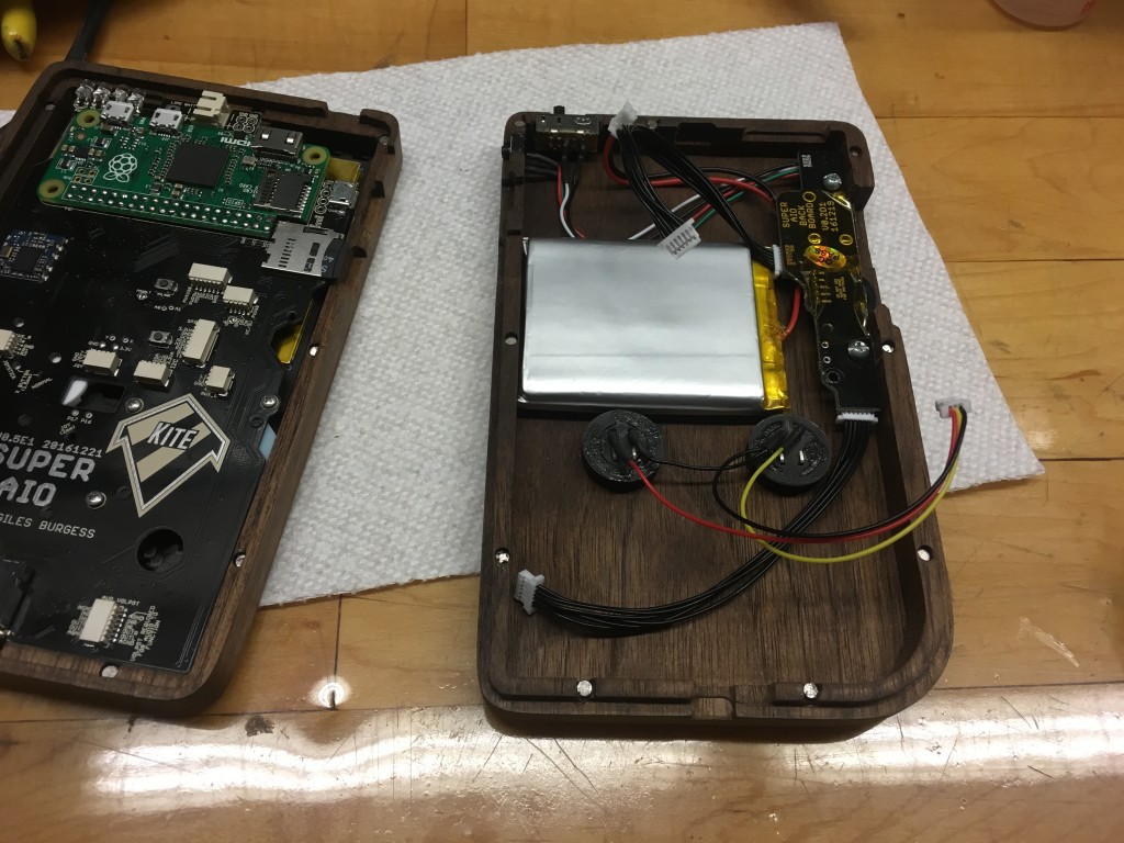
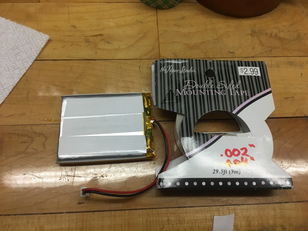
Next I installed the battery. First I tried using foam servo tape but found it to be too thick so I used double-sided scrapbooking tape instead. The battery wires were routed under the back-board PCB to keep them neat.
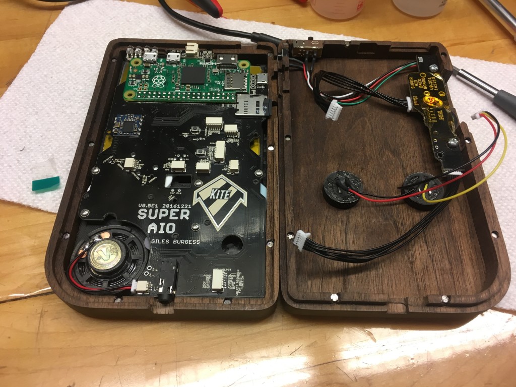
Now that everything was place I brought the two halves together and followed the SAIO instructions for plugging in the ribbon cables. I also did one last test to make sure everything works before putting the case together.
Next I CAREFULLY brought the two halves of the case together, using my finger to relocate any wires as needed. Once the wires were in place everything came together smoothly and the magnets kept it there with almost no gap.
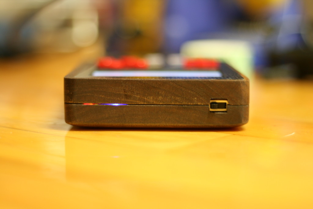
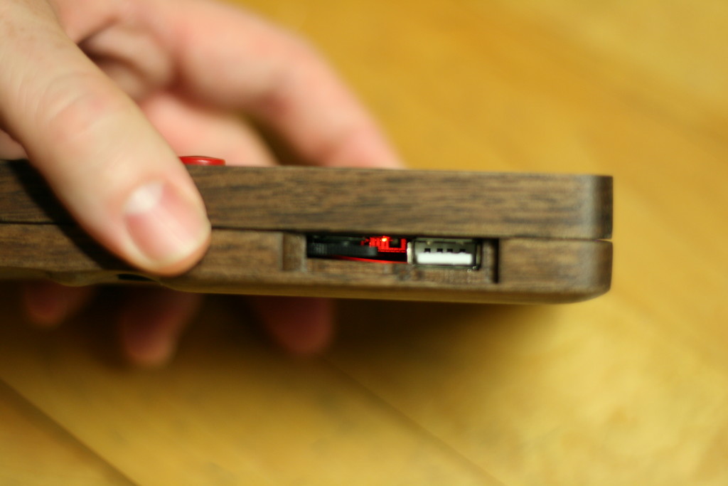
What little gap did occur was actually a feature as it let the status lights from the SAIO board shine through (I totally planned that. )
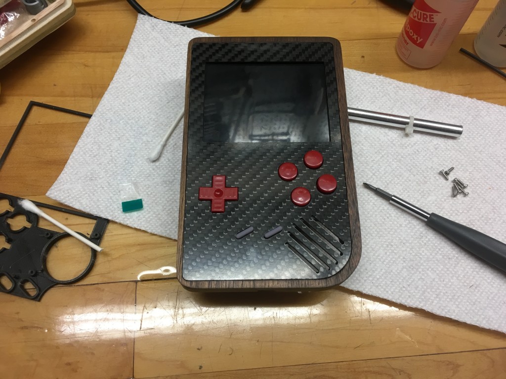
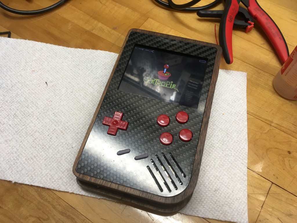
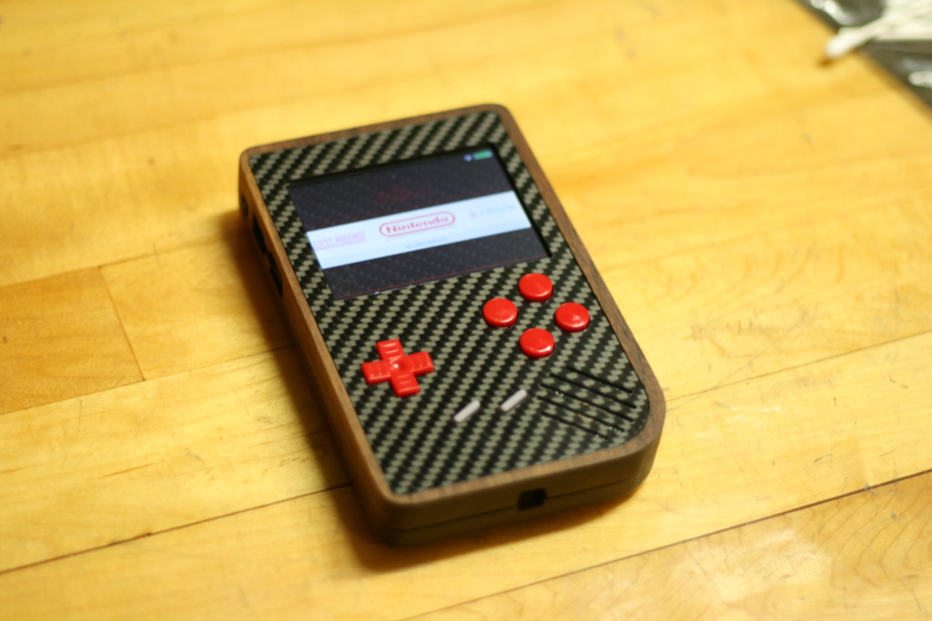
Finally the PiBoy was booted and I loaded up my collection of ROMs using a USB stick.
If you don’t have ROMs, just know that it’s not exactly legal to download them. Because of this, I’m not going to tell you that you can go to your favorite search engine and type in “NES ROMs” or “SNES ROMs” and find thousands of hits (just make sure you have your pop-up blocker enabled and your antivirus is up to date.)

CONCLUSION
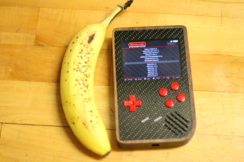
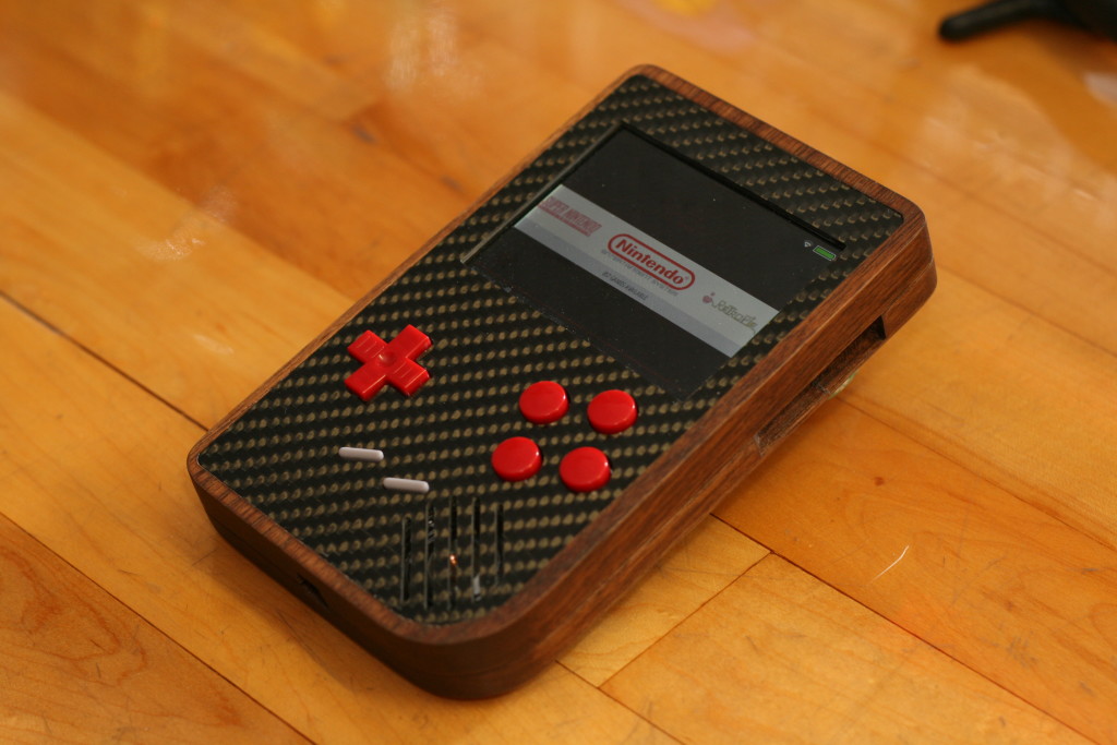
Overall this was one of the most difficult enclosure products I’ve done due to the number of details but it was also one of the most rewarding. The finished product is slightly larger than an original GameBoy and it plays as well as it looks. The button action is actually better than the USB SNES controllers I have and gets complements from whoever plays it. With the battery fully charged I am able to get 5-6 hours of gaming – about 2x that of a Nintendo Switch! Cost wise, I have around $150 in it not including the materials I already had. If you wanted to build one from scratch I’d guess you could do it under $200, less if you used guitar pick guard or something less expensive for the top plate.
SOFTWARE
- CNC CAD / CAM – Vectric Aspire
- CAD (3D printed parts) – AutoDesk Fusion 360
- Emulator – RetroPie
MACHINES
BOM
- 3/4″ American Walnut (at least 16″) – Link
- 1/16″ Carbon Fiber Panel – Link
- Raspberry Pi Zero – Link
- Class 10 16GB MicroSD Card (you could go bigger for more games) – Link
- Kite’s Super AIO Kit – Link
- 1/8 x 1/8 Neodyium Magnets – Link
- 2 x 3/16 4-40 Screws – Link
- ¼” #1 Screws. Mcmaster Carr 99461A615 – Link
- Kapton Tape – Link
- 6mm Tactile Buttons – Link
- 2500 MAh LiPo Battery – Link
- GameBoy Buttons / Speaker / Rubber Pads – Link
- Watco Danish Oil – Dark Walnut – Link
TOOLS
- Soldering Iron and Equipment – Link
- Hobby Knife – Link
- Medium CA Glue – Link
- 5min Epoxy – Link
- Dremel #569 Grout Removal Bit – Link
- 1/8 2-Flute Straight Bit – Link
- 1/8″ Ball Nose Bit – Link
FILES
ADDITIONAL PHOTOS
- Google Album – Link

Hello, your project is fantastic. I would very much like to be able to replicate your project. But I only have one 3D printer. Could you convert the files from the wood parts to .stl?
Thanks for the kind words! I’ll see what I can do. The last time I tried to use the .STL export it didn’t work but they’ve done some updates since then. I’ll try again to see if it works.
Let me know when you get it done. Thank you so much!
[…] over to Michael’s blog to see tons of details of how he machined the case and put it all […]
Love this build! I am a CNC metalworker (3,4 and 5 axis CNC mills) and I could make your gameboy case out of aluminium (or even Titanium if I could get hold of a few pieces!) Would you share your CAD files (DXF maybe or even a 3d model – IGES or step files)? I’d make one from ally, probably get it anodized and have a perspex front plate. I noticed the Super AIO pcbs aren’t available now either – shame…
Absolutely epic work. If you ever fancy taking orders to make these I would be first in line!
[…] The Raspberry Pi is possibly the world’s most popular emulation platform these days. While it was never intended to serve this purpose, the fact remains that a small, compact computer with flexible I/O is ideally suited to it. We’ve featured a multitude of builds over the years using a Pi in a mobile form factor to take games on the go. [Michael]’s build, however, offers a lot more than a few Nintendo ROMs and some buttons from eBay. It’s a tour de force in enclosure design. […]
[…] El Raspberry Pi es, posiblemente, el mundo’s más populares de la plataforma de emulación de estos días. Mientras que la intención nunca fue a servir a este propósito, el hecho es que un pequeño, compacto equipo con e/S flexible es ideal para ti. We’cinco contó con una multitud de generaciones a través de los años el uso de un Pi en un móvil factor de forma para tomar con juegos. [Michael]’s construir, sin embargo, ofrece mucho más que un par de ROMs de Nintendo y algunos botones de eBay. ’s un tour de force en el diseño de la caja. […]