PiPad Build
Two weeks before I had to leave for Maker Faire Bay Area 2013, I decided it was time I built an enclosure for the PiPad. I’d been helping a guy in the Shed Tech Support queue that needed some help with his Maker Faire project, and thought “You know, I want a Maker Faire project too.” Crazy – right? I had all the parts, so really the only thing holding me back until this point was a deadline. According to Parkinson’s Law “work expands so as to fill the time available for its completion” so at two weeks, I didn’t have much time for expansion. I started on some conceptual CAD work for the project before so I had a *slight* idea of what I was doing.
Design Goals:
I like simplistic, functional design. I don’t like extra crap that doesn’t do anything and I enjoy fun, hidden features. I also like for my projects to look as “sexy” as possible. I thought about hollowing out a book and putting it in there (like Penny’s book computer from Inspector Gadget) but decided to go with a stand-alone tablet form-factor. Since I wanted to let the PiPad keep me company on flights, the enclosure had to look as factory as possible, while remaining accessible and usable. The last thing I want is for it to freak out the TSA or the old lady sitting next to me.
Bill of Materials:
- Frame Material – 1/2″ Baltic Birch Plywood (local lumber supply)
- Backing Material – 1/16″ Carbon Fiber Sheet (I buy scraps from here and happened to get a flawless, large piece. Don’t count on that!)
- Finish – Watco Dark Walnut Oil Finish – Amazon
- Latch / closing – 14 – NdFeB Magnets – Amazon (These are *probably* overkill.)
- Battery – Anker Astro3E 10,000mAh battery – Puts out 3A @ 5V! Gives me about 6hrs of battery life.
- WiFi – I’m using this adapter from Monoprice, but this one from Amazon should work well too.
- USB HUB – IOGear Micro Powered USB Hub (removed from casing)
- Bluetooth – After experiencing issues with an AZIO bluetooth dongle, I switched to one like this and it worked great.
- Keyboard – Adesso Bluetooth Mini Keyboard
- Main brain – Raspberry Pi Model B (Ethernet and 1 USB port removed.) Edit – The Raspberry Pi Model B has been discontinued. The most recent version is the Raspberry Pi 3 Model B+ which is available here. You’ll need to retool the build for this board or try to find an old Model B if you’re trying to recreate it exactly.
- Heat Sinks for Raspberry Pi – Amazon (There’s no airflow in the case so I figured this was a good idea.
- Misc USB ends – Male A (3), Micro (1), Female A (I hacked an extension I had laying around.)
- Screen – 10″ Capacitive Touch Screen with LDVS Adapter from Chalk-Elec.com. I had a great experience with this company (they are based in Malaysia) but have heard mixed reviews from others.
- Brightness adjustment – 10K Potentiometer (I had this lying around – it replaced the light sensor that came with the screen / LDVS adapter.)
- GPIO – Ribbon cable and connectors (male and female) for GPIO.
- Power switch – Waterproof Metal On/Off Button with White LED Ring – From Adafruit.
- Screen / backing adhesive – Permanent double stick scrapbooking tape -Picked up locally from Hobby Lobby (if this ever fails I’ll get the 3M stuff they use on iPads)
- Hinges – 1″ Brass hinges (Picked up locally from Hobby Lobby)
- Extension for battery charging – Micro to Mini USB adapter – Amazon (to extend the charging port to outside the case.)
- Amplification – Fiio E5 Headphone Amplifier (Now replaced by the Fiio E6) – The Pi doesn’t have an on-board amplifier. This miniscule amp works and sounds great and pumps out enough volume to hear on planes.)
- Audio extension – 3.5mm Audio jack (like this) and hacked extension cable.
- Probably one or two other things I’m forgetting.
Associated Files:
Everything I used in one .zip file. (Now available on GitHub!)
Construction:
The principle components of the enclosure are 1/2″ Baltic birch plywood and 1/16″ carbon fiber (for the back). I designed the cut files in Vectric’s incredible Aspire CAD/CAM package (though everything I did was in 2D) and used the image tracing feature to digitally recreate the components to ensure enough clearance. The components were placed on a scanner and loaded into the software so I could manipulate them for what I thought would be the best layout. Fortunately the folks at Chalk-Elec published a datasheet for the display with dimensions, although the corner radius wasn’t listed (it’s 10mm if you’re wondering.) I wanted to make the back the same size as the LCD panel, but the carbon fiber scrap I had was slightly too small so I had to re-size. I intended to machine the slots for the components using multi-sided machining but kept getting my layers confused. Because I was short on time and had limited material, I decided I’d hand cut the necessary slots (which ended up being easier than I thought.) I bought a new spiral downcut bit for a smooth finish and turned my CNC machine loose on the wood. After a bit of sanding and an inspection, I machined the carbon fiber with a 1/8″ carbide Dremel bit, sanded, and did a test fit. Everything lined up!
Next I laid out the electronics and marked out where I needed to cut access holes in the plywood frame. After everything was marked I cut though one layer of plywood with an Exacto knife, popped out the layer, and continued down until the slot was deep enough. Then I popped in the component, placed on the top, and checked to see if any more material needed removed. The SD card slot was another challenge. After measuring where the SD card would be and marking the area that needed removed, I taped a level onto my drill and drilled a series of holes using a 1/8″ bit. Then I used a coping saw to remove the rest. The results were a bit jagged so I cut a strip of sandpaper and worked it though the slot until smooth. Once I was satisfied with the holes, cut out the area for the hinges and mounted them into place. I’m not sure if was just me or a “thing” with hinges, but once installed the frame didn’t quite line up. Despite tweaking as much as I dared, it still wasn’t perfect. I ended up getting mad, mounting a belt sander in a vise and sanding the heck out of it until it lined up 100%. Once I was happy with it, I drilled in holes for the magnets. After I got the polarity right (yeah – I messed up a few times) I glued them in. Once dry, I removed the hinges and applied several coats of rub-on varnish.
When the varnish dried, I glued the carbon fiber backing in place, then installed all the components and ran / soldered the wiring. I put the whole thing together (nothing anchored in place yet) and turned it on. The power indicator blinked on and after a few tension-filled seconds, it booted! Everything including the touchscreen functioned as expected (which NEVER happens for me). I shut it down, finalized the layout, and started anchoring the components in place using either hot glue (I used this mainly for the wiring), permanent double sided tape, and foam tape. The display was affixed “Apple Style” using some crazy strong permanent tape around the inside edge. I clamped the battery and screen down and allowed the tape to cure over night to ensure a good bond.
The next day I realized I had a problem – the touchscreen wasn’t tracking my finger and a section of the screen was the wrong color. I quickly realized that I didn’t have enough clearance between the back of the Pi and the back of the screen. At this point I only had a few days before I left for Maker Faire, so I started freaking out a little. The Pi had to stay in it’s current location and was already as low as I could get it due to the SD card slot. I tried bending the metal around the USB port down but the issue persisted. So I got out my exacto knife and some pliers and pried the metal USB housing off completely. Then I took some cutters and completely removed the top USB port connections and plastic. That had to do it, right? Nope.. now the Ethernet jack was touching. While it didn’t distort the screen it was causing the touch to be erratic – so out came the soldering iron and away it went! Essentially I converted my Raspberry Pi Model B into a Model A with 512mb of RAM. But importantly, it worked and the PiPad was complete!
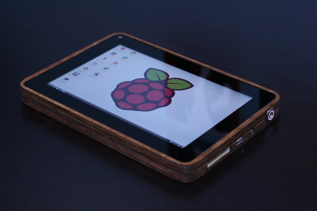
Conclusion:

This image was taken while on my fight from Ohio to San Francisco (using a mouse because the touch-screen doesn’t work with RaspBMC.) The PiPad preformed flawlessly and didn’t raise an eyebrow going through security. On the plain though, a flight attendant kept walking by, looking closely at the homebuilt gadget I had on my tray table playing Talladega Nights. At one point I could feel her looking over my shoulder and was sure she was going to say something. She nudged me (I thought it was over at this point) and said “I love that movie – you’re coming up to the best part!” I’ve taken the PiPad on every flight I’ve been on since then and it’s never raised an eyebrow.

I’d e-mailed Eben Upton a few times for work, but didn’t have the chance to meet him at Maker Faire Bay Area. I did catch up with him at Maker Faire New York though. Eben is probably the most humble, down to earth person I’ve ever met – I really can’t say enough about him. After a long chat I showed him the PiPad. After several compliments and a few minutes of playing with it, Eben graciously signed the back at my request. His signature looks amazing on the carbon fiber!
Future Upgrades:
I’ve been considering adding a camera and IR sensor but am not quite sure if I want to bugger up the case. I do need to figure out how to get the touch screen working in Raspbmc – evidently it isn’t compiled with the nTrig driver. I may someday build a version 2.0 if I get ambitious..maybe if the Pi gets an upgrade. We’ll see!

Hey
How did you take the USB Hub and Ethernet Hub off? Have you done this only with ansoldering bolt or must you make it in a spezific way?
sorry for bad English
thanks fr replying
I used a soldering iron and desoldering braid. It took about 10min or so as I recall. Not too bad.
Now it is the time for a rugged outdoor version!
That’s not a bad idea! Prhaps for the 2.0 version..
Hello my name is kyle, I’m building the pipad is there something cheap and easy to do for the case I don’t have access to a few things I need for a carbon and wood case.
Hi Kyle,
The easiest thing to do would to go to a craft store and find a wooden box big enough for the screen. Then just cut out the lid, insert your electronics, and drill holes for the appropriate ports. I’ve also heard of some folks using deep picture frame and display boxes.
Hello,
Have you got your enclosure in TLS format, for print it in 3D ?
Thanks
I don’t, but a gentleman who commented earlier did. The files are available here – http://www.thingiverse.com/thing:346114
I don’t understand how the 12V screen runs on a 5V battery. Could you briefly explain that?
Does the LVSD cable lower the required voltage?
No, but it does operate at 5V which is the same voltage required by the Pi and that is put out by the USB cell charger battery pack.
I’m not using a 12V screen. The screen I’m using is powered by 5V just like the Pi. If you did want to use a 12V screen you’d need either a 12v battery (though most would work with 11.1V hobby type LiPo) and a voltage regulator or a 5V battery with a step up / boost regulator (assuming it can put out enough current to run the screen.)
how much does it cost
It cost me around $350 or so to build.
woah! that’s a nice tablet that’s also very cheap, (the price, NOT saying its bad, cuz its not at all) costs less than an ipad anytime!
Thanks! I don’t think I’d call it cheap but it is pretty cool (and different.) I do appreciate your enthusiasm!
Hello 🙂 ,
http://l.bitcasa.com/9z3OrXa8 have been moved to https://drive.bitcasa.com.
Could you give us a new link to download files?
Thanks for all 🙂
Regards
Hello,
Sorry about that. I’ve been moving some things around to make them easier to access as well as upgrading the site. The files can now be found on GitHub.
-Michael
Hi Michael, the PiPad idea is fantastic! I see people have used 3D printer, plexiglass and of course wood – maybe I will try carving it into stone so its a proper tablet!
I am going to try this project out with my 13 yr old son – will be great fun. I noticed that the link to your CNC files on Bitcasa is no longer working, do you mind updating the link? Thanks!
Hey Kevin,
Sorry about that. The files are now available on GitHub. Should be a much better experience than Bitcasa (just canceled my subscription with them.)
Let me know what you think of the new site!
-Michael
Hi Marc,
I have your IPAD found on the Internet and would like to recreate it. Unfortunately I can not I can not find the cad file for the frame. The partlist for the components I have found and have all the parts found. I would appreciate if you could send me the cad file. My email address nordcux@aol.com.
I wish you a Merry Christmas.
Michael Willenbrink from Germane
Sorry, my englisch is not perfeckt.
Hi Michael,
The files have been moved to GitHub. Should make life much easier.
Good luck with the project!
-Michael
Hi,
the Link to the Associated Files isn´t working.
I would really like to build my own pad, too.
Could you please check this link?
Thanks,
Malte
does it over heat? Did you consider a built-in ventilation system?
Hello,
I was a bit concerned about this myself so I added heatsinks. Having many hours on it now, I don’t think they are necessary. At max load the interior gets warm but still preforms normally. I’ve never had it overheat even when running for 6+ hours in the outdoor heat of Maker Faire.
Hope this helps!
-Michael
Hi Michael,
I am trying to get a Rasp model B+ getting to work with an Android version.
I preparred the SD card as described here:
https://www.mepits.com/project/180/DIY-Projects/How-to-Install-Android-on-Raspberry-Pi-?
I connected the Raspberry with TV, keyboard, wireless WIFI USB dongle and finally with the 5 V powersupply.
What happend?: Nothing…. What did I do wrong ?
How to fix this?
Thanks for any help in advance,
Joop
Hi Joop,
Running Android on a Pi is still in the experimental stages at best. Definitely a work in progress. I’ve kept my eye on the development but haven’t tried it myself. Personally, while I find the idea of running Android on the PiPad alluring, there are many inexpensive ($50-$100 and sometimes less) tablets out there that are made for it and will give a much better experience.
Not sure what might be going wrong – I’d double check your formatting and check your power. Many TV USB ports only put out 500mah. Powering the Pi, a keyboard, and WiFi might be causing brownouts. Make sure you’re using at least a 1 amp supply and try using a powered hub (of course, first verify that your SD card is properly loaded and bootable.)
Hope this helps! Let me know how it goes.
-Michael
Hi,
Is there anybody who could create a 3D model so that I could let it be created by a §d printing service?
So how are you supplying power to the screen? The hdmi to lvds converter you plugged into the pi has a circle power spot and you put that right next to the edge of your frame, or did I just miss something?
Word to the wise Chalkboard Electronics is difficult to deal with. Michael had success with them but my experiences have been extremely poor. Products ship late and the customer service responds weeks later, if ever.
Michael, is there no where else to get a capacitive multi-touch?
-Eric
Hi!
This display is fine to build my pipad? requires the module LVSD?
http://www.chalk-elec.com/?page_id=1283#!/10-universal-LCD-with-HDMI-interface-and-capacitive-multi-touch-pre-sale/p/42545413/category=3094861
Thanks
Marco
Hey micheal I just got the piscreen to work with my raspberry pi and upgraded my pipad to android using the android mini pc. Thanks again for all your great help on my projects.
ps. sent from my pipad running android
I would love this with Eink display. To display/read PDFs…
will the chalk-elec. screen run off just 5v .1amp
Hello my name is Caleb, I am in high school and i am attempting to build my own pi pad. I purchased a different screen than you recommended, a 7” capacitive multi-touch IPS LCD with 1280×800 resolution, from the chalk-elec website. I am having some difficulty figuring out how to connect the LVDS adapter to the screen because it has different connectors, than the one you used. If i need to break out the wires in the USB cable from the screen to the LVDS board, which wires are the power and what pins on the LVDS board are the power pins?
Hi Caleb,
The 7in screen uses a small barrel jack connector for power (it’s the one to the right of the USB port.) You’ll need to supply this connector with 5VDC, center positive. The USB jack is for the touch sensor – you’ll need a USB A to Mini connector to hook it into the Pi’s USB port. Finally, the LCD has a mini HDMI Port. You’ll need a miniHDMI to HDMI adapter or cord to plug it into the Pi. Here’s a labeled diagram
Let me know how it goes!
-Michael
In case of RasPi Model B+ you can also try to power LCD right from USB cable (the same that used for touchscreen interface). Previous RasPi models had low current rate on USB port (just 120mA), but they improved it in Model B+.
Is there instructions for a 7″ tablet or do I just pack things in a little tighter?
Not yet, though I have though about building a PiPad mini. You’d definitely need to cram things in there a tighter but I think it would be completely doable. Let me know if you do it!
-M
With a Raspberry Pi B+, you remove the need for a powered USB hub (I tried). It is then easier to make things more compact, albeit a little thicker.
Hey Ben,
The Chalk-Elec screen uses the n-trig driver. Did you find this article (http://www.chalk-elec.com/?p=1592)? Basically, it points you here (http://source.android.com/devices/tech/input/).
Hope this helps!
-Michael
i looked at the pages but the android one was really confusing sorry to ask this but is there a driver to install? or if not how could i get the touch-function working?
ps. posted from my pipad
Just got my banana pi to work with the chalk-elec screen running android but i was wondering if there were any drivers to install for the touch function because that hasn’t been working, please help i haven’t been able to find anything on google.